The following is a solution to the given problem.
Please compare the given solution with your solution and submit a
self-critique of any error(s) in your solutions, and/or and additional questions
or comments you might have.
Simply copy your posted document into a text editor and insert revisions,
questions, and/or self-critiques, marking your insertions with ####.
Submit using the Submit Work Form.
Sketch a vector representing a 10 Newton force which acts vertically
downward.
• Position an x-y coordinate plane so that the initial point of your vector is
at the origin, and the angle of the
vector as measured counterclockwise from the positive x axis is 250 degrees.
This will require that you 'rotate' the x-y coordinate plane from its
traditional horizontal-vertical orientation.
The force vector remains vertical.
The coordinate system in standard orientation will have the y axis vertical, the
x axis horizontal. The force vector will be along the negative vertical axis.
The coordinate system then rotates until the force vector is at the 250 degree
position. This will require rotating the coordinate system counterclockwise
through an angle of 20 degrees, so that the x axis points in a direction 20
degrees above horizontal, the y axis 20 degrees to the 'left' of vertical. The
negative y axis will then be rotated at 20 degrees from the original vector.
• What are the x and y components of the equilibrant of the force?</p>
The x and y components of a vector of magnitude 10 N, directed at 250
degrees (as measured counterclockwise from the positive x axis) are
x component: 10 N * cos(250 deg) = - 3 N (very approximately) and
y component: 10 N * sin(250 deg) = -9 N (very approximately.
The x and y components of the equilibrant are equal and opposite to those of
the force, so:
x component of equilibrant: +3 N (equal and opposite to -3 N component
of the original vector)
y component of equilibrant: +9 N (equal and opposite to -9 N component
of the original vector)
The process of rotating the axes is depicted below.
We begin with a vector representing the 10 N force acting vertically
downward.

The next figure shows the x and y axes in their 'traditional' horizonal
and vertical directions, with the initial point of the 10 N force vector located
at the origin:
In the next four figures the x-y coordinate system is rotated in the
counterclockwise direction, 5 degrees at a time, until it has been rotated 20
degrees in the manner specified above. The 10 N force vector maintains its
original position and direction.
- We see that the negative y axis 'swings out' away from the force
vector, until it makes an angle of 20 degrees with respect to the negative y
axis.
- With the axes in this position, it should be clear that the force
vector makes an angle of 250 degrees with the positive x axis, as measured
in the counterclockwise direction.
In the last figure the original vector now lies at 250 degrees as measured
counterclockwise from the positive x axis.
- If we start from a point on the positive x axis and move
counterclockwise around the origin, we reach the positive y axis after
moving through 90 degrees of arc, then 180 degrees as we pass through the
negative x axis.
- If we were to continue until we reach the negative y axis we would be
at 270 degrees. However we encounter the vector before we get to the
negative y axis, as a position where we're 20 degrees short of that axis.
- So our angle, as measured counterclockwise from the positive x axis,
is 250 degrees.
The first figure below shows the projection lines from the terminal point
of the force vector to the x and y axes.
- The projection line that runs from the terminal point of the vector
to the x axis is parallel to the y axis, perpendicular to the x axis.
- The projection line that runs from the terminal point of the vector
to the y axis is parallel to the x axis, perpendicular to the y axis.
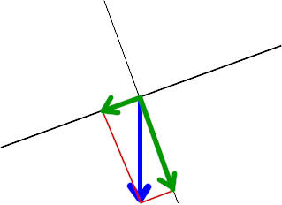
The second figure below shows the x and y projections of the original
force vector.
- The force vector has magnitude 10 Newtons, and is directed into the
third quadrant, at angle 250 degrees.
- The x projection is indicated by the 'green' vector, directed along
the negative x axis.
- The magnitude of the x projection is about 3 Newtons.
- The projection is directed in the negative x direction.
- We therefore say that the x component of the force vector is
about -3 Newtons.
- The y projection is indicated by another 'green' vector, this one
directed along the negative y axis.
- The magnitude of the y projection is about 9 Newtons.
- The projection is directed in the negative y direction.
- We therefore say that the y component of the force vector is
about -9 Newtons.