Class 091123
Things you really should know at this point
You should know the meanings of the following expressions:
- G M m / r^2
- -G M m / r
- omega = sqrt(k / m)
- tau_net = I * alpha
- I = sum(m_i r_i^2)
- `dW = tau `dTheta
- sum(F_i) = 0
- sum(tau_i) = 0
`q001. Identify each of the expressions listed above and explain its meaning.
^^^^
&&&&
`q002. What relationship would you use to find each of the following, and how would use use it?
- The mass of a planet, given orbital velocity and radius of its circular orbit.
^^^^
&&&&
- The orbital velocity of a planet, given the radius of the orbit and the orbital period.
^^^^
&&&&
- The gravitational potential energy of a satellite, relative to infinity, give the mass of the planet, the mass of the satellite, and the radius of its circular orbit.
^^^^
&&&&
- The centripetal force acting on a small satellite of known mass in a circular orbit about the planet, given the mass of the planet and the distance of the satellite from the center of the planet.
^^^^
&&&&
- The kinetic energy of a small satellite, given its mass, the mass of the planet, and the radius of the satellite's circular orbit about the planet's center.
^^^^
&&&&
- The centripetal acceleration of an object moving in a circle, given the radius of the circle and the object's speed.
^^^^
&&&&
- The speed of an object moving around a circle, given its angular velocity and the radius of the circle.
^^^^
&&&&
- The directions of the radial vector and the centripetal acceleration vector, given the angle and magnitude of the velocity vector for an object moving counterclockwise around a circle.
^^^^
&&&&
- The work done by a given torque acting for a given time interval, given also the average angular velocity during that interval.
^^^^
&&&&
- The x components of the radial, velocity and centripetal acceleration vectors, given the magnitude and direction of the radial vector for an object moving around a circle, as well as the magnitudes of the velocity and centripetal acceleration vectors.
^^^^
&&&&
- The angular velocity of the reference point in the circular model of simple harmonic motion, given the mass of the object and the restoring force constant k.
^^^^
&&&&
- The period of simple harmonic motion, given the angular velocity of the point moving around the reference circle.
^^^^
&&&&
- The moment of inertia of a strap loaded with dominoes and magnets, given the masses of the strap, dominoes and magnet, the length of the strap, and the positions of the dominoes and the magnets.
^^^^
&&&&
- The restoring force constant k given the graph of F vs. x.
^^^^
&&&&
Repeat previous experiment
Today you repeated the experiment from last Monday's class, involving the rotating strap with the dominoes and magnets.
Note the following:
- You are to observe three systems, one consisting of just the strap with the dominoes at the end, the second also including magnets at the end, the third with the magnets moved halfway back to equilibrium.
- The rubber band system used to accelerated the system should exert the same force through the same distance on every trial.
- You need to time every trial so you can determine the angular accelerations, which from some reported results appear to differ from one system to the other.
Calibrate a rubber band chain using 1 domino, 4 dominoes and the number of dominoes which when suspended stretches your rubber band system to the length used in this experiment.
Having completed your observations, you should repeat the analysis of that experiment, as instructed in the 091116 notes, and submit. You may submit only that part of the document; this time use the title 'ic_091116_exp_repeat'.
If you have already submitted work on this experiment, please note:
- If you did the entire experiment correctly, including the analysis, you do not need to do this.
- If you previously analyzed your data correctly but didn't include all trials, you should analyze today's data, but you may just submit a synopsis of your data and your results.
`q003. Sketch a graph of the force stretching your rubber band system, in domino weights, vs. its length in cm. Sketch the straight line you think best fits the data.
What is the slope of your graph, in domino weights per cm?
^^^^
&&&&
What is the slope of your graph, in Newtons / m (you may assume that a domino weighs .2 Newton)?
^^^^
&&&&
The slope of your straight line was affected by the third point, where the rubber band was stretched to the length used in the experiment. We might get a slightly different result using only the 1- and 4-domino points. What is the slope, based only on these points?
^^^^
&&&&
What is the meaning of the slope of this graph?
^^^^
&&&&
How does the slope change if you increase the length of the chain?
^^^^
&&&&
How does the perceived 'stiffness' of the rubber band system change with increasing chain length?
^^^^
&&&&
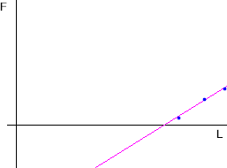
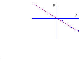
Your F vs. L graph; F vs. x graph
The graph below is similar to that you obtained for F vs. L when you calibrated your rubber band, with the straight line approximately fitting the three data points. (The line has been extended here below the horizontal axis, which would correspond to negative forces; your rubber band chain won't exert forces when its length falls below its unstretched length, so this isn't realistic, but we will soon see examples where this extension of the line is necessary and realistic).
We sketch a vertical line through the horizontal intercept of the straight line:
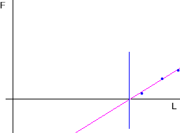
The horizontal intercept is our equilibrium point--the point at which the force exerted by the rubber band system is zero.
It will simplify our analysis to measure horizontal position relative to the equilibrium point.
We will therefore replace our original coordinate system with one whose origin is at this equilibrium point. So we will use our new vertical line as the y axis, and will again label the vertical coordinate F, for force. We will label the horizontal coordinate x.
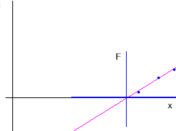
Our x coordinate now represents the horizontal position relative to the equilibrium point. We can now do away with our original y axis, and we obtain the graph below:
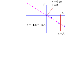
This graph depicts the force exerted by the rubber band as a function of the distance its end is pulled from the equilibrium force. However there is one thing we still need to do to indicate force vs. position. The force exerted by a rubber band at its end is in the direction opposite the direction in which that end is displaced (i.e., if you move the end to the right, the resulting change in the force is to the left; the rubber band 'pulls back' against you).
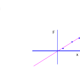
So in order to depict the force exerted by the rubber band, positive values of position x should be associated with negative forces. Force and position should have opposite signs. So our final graph is as shown below:
The straight line depicted by the graph goes through the origin. If we denote its slope by -k, then its equation is
- F = - k x.
To get the force for position x, provided we know the value of k, we just substitute that value of x into the equation F = - k x and we get the force.
- k is called the force constant.
Now let's assume that x has some specific value A:
- If x = A, then
F = - k x = - k A.
It's worth noting that when x = 0 we get F = - k * 0 = 0.
The forces as x = 0 and x = A are indicated on the figure below. The x = A position corresponds to the vertical line labeled 'x = A', and the resulting force is indicated by the vertical projection line:
`q004. We want to determine the work done by this rubber band as we stretch it by moving its end from the equilibrium position to the x = A position. To do so we need to find the average force exerted by the rubber band and the corresponding displacement as we move between the two positions.
- What is the force exerted by the rubber band at x = 0, and at x = A?
^^^^
&&&&
- What therefore is the average force exerted between these two positions?
^^^^
&&&&
- Through what displacement is this force exerted?
^^^^
&&&&
- What therefore is the work done by the rubber band over this interval (be very careful about the signs of the force and the displacement so you get the right sign for the work)?
^^^^
&&&&
- Assuming the rubber band force to be conservative, what is the corresponding change in the potential energy of the system?
^^^^
&&&&
Experiment
Using the same rubber band chain you calibrated in the preceding experiment, suspend a 4-domino mass, allow the suspended system to oscillate at its natural frequency (being careful that the rubber band never goes slack), and count oscillations for 10 seconds.
`q005. If k is the slope of the force vs. length graph for your rubber band system, and m the mass of the dominoes, then what is omega = sqrt(k / m)?
^^^^
&&&&
The units of your calculation should have worked out to 1/s, or s^-1. Your solution should have showed how this works out. We aren't going to go into the details of exactly how (it's related to the fact that a meter of arc divided by a meter of radius is a radian), but a radian also appears in the result, and proper unit turns out to be rad / s or rad s^-1.
If a point moves around a reference circle of radius 3 cm, at the angular velocity you just calculated, then what is its speed in cm / s?
^^^^
&&&&
What therefore is its centripetal acceleration?
^^^^
&&&&
If the reference-circle point represents a mass of .8 kg, then what are the KE of the object, and the centripetal force holding it in its circular path?
^^^^
&&&&
If the reference-circle point starts at the positive x axis, then after .1 second, what will be the angle of the r vector?
^^^^
&&&&
`q006. This problem is a continuation of the previous.
To answer the following it is suggested that you first sketch the reference-circle figure for each of the given instants, use the figure to estimate the requested quantities, then use sines and/or cosines to refine your estimate with an accurate result:
At the .1 second instant:
- What is r_x, the x component of the r vector?
^^^^
&&&&
- What is the angle of the v vector and what is its x component v_x?
^^^^
&&&&
- What is the angle of the a_cent vector and what is its x component a_cent_x?
^^^^
&&&&
Answer the same questions for the instant .2 seconds after the start.
^^^^
&&&&
`q007. One circuit around the reference circle corresponds to an angle of 2 pi radians, or 360 degrees.
- How many radians, and how many degrees, would correspond to motion halfway around the reference circle?
^^^^
&&&&
- How many radians and how many degrees would therefore correspond to motion 1/4 of the way around the reference circle?
^^^^
&&&&
- How many radians and how many degrees would correspond to motion halfway around the first quadrant? How many degrees and how many radians to 2, 3, 4, 5, 6, 7 and 8 times this angle?
^^^^
&&&&
- How many radians and how many degrees would correspond to motion 1/3 of the way around the first quadrant? How many degrees and how many radians to 2, 3, 4, 5, 6, 7, 8, 9, 10, 11 and 12 times this angle?
^^^^
&&&&
`q008. At the angular velocity corresponding to the system you observed:
- After how many seconds would the reference point be at the 30 deg, 120 deg, 210 deg and 300 deg positions?
^^^^
&&&&
- Assuming amplitude 3 cm, what would be the y components of the position, velocity and centripetal acceleration vectors at each of these positions?
^^^^
&&&&
Areas of difficulty from previous assignments
`q009. Reason out the units in each question:
- What are the standard units of G M m?
^^^^
&&&&
- What are the standard units of G M m / r^2?
^^^^
&&&&
- What are the standard units of G M m / r?
^^^^
&&&&
- What are the standard units of G M / r?
^^^^
&&&&
- What are the standard units of G M / r^2?
^^^^
&&&&
- What are the standard units of tau * omega?
^^^^
&&&&
- What are the standard units of I * omega?
^^^^
&&&&
- What are the standard units of I * alpha?
^^^^
&&&&
- What are the standard units of I * omega^2?
^^^^
&&&&
- What are the standard units of omega * `dt?
^^^^
&&&&
- What are the standard units of r * omega?
^^^^
&&&&
- What are the standard units of alpha * r?
^^^^
&&&&
`q010. Answer without using your calculator. You won't learn anything by using the calculator, and you stand a good chance of getting the wrong answer if you do use the calculator. You need to be able to do this, and even top students in physics often come into the course not knowing how to calculate with powers of 10.
- What is 10^-11 * 10^24?
^^^^
&&&&
- What is 10^-11 / 1 000 000?
^^^^
&&&&
- What is 10^18 / 10^-11?
^^^^
&&&&
- What is 10^-11 * 10^24 * 10^22 / 100 000 000^2?
^^^^
&&&&
The idea of SHM
Reference circle summary
For a point moving counterclockwise around a circle, if the angular position of the r vector is theta then
- the velocity vector v is at angle theta + 90 degrees and
- the centripetal acceleration vector a_cent is at angle theta + 180 degrees,
all angles measured counterclockwise from the positive x axis.
The idea of SHM
If mass m is subject to net force
- F_net = - k x
then if the object is given an initial velocity and/or is pulled away from the equilibrium point at x = 0 and released, its position can be modeled by a point moving around a reference circle with angular velocity
- omega = sqrt(k / m).
The position, velocity and acceleration of the object are respectively the x components of the r, v and a_cent vectors of the reference circle.
- The motion of the mass is said to be simple harmonic.
- Simple harmonic motion occurs if and only if the net force is of form F_net = - k x.
Assuming the net force to be conservative, there are no nonconservative forces acting on the oscillator so `dW_nc_on = 0 and `dPE + `dKE = 0. Thus the total of the potential and kinetic energies is zero.
`q011. A pendulum, swinging freely with an amplitude much less than its length, is one example of a simple harmonic oscillator (another being a mass suspended from an ideal spring or rubber band chain and oscillating up and down).
At position x = 3 cm a certain pendulum has kinetic energy 4 Joules and potential energy 2 Joules.
- What is its PE when it comes to rest at an extreme point of its swing?
^^^^
&&&&
- What is its KE when it passes through its equilibrium point?
^^^^
&&&&
- What is its KE at a point where its PE is 5 J?
^^^^
&&&&
- What is its PE at a point where its KE is 3 J?
^^^^
&&&&
Complete characterization of SHM
What follows is a series of more precise statements about SHM. Next week we will work out the meaning of these statements through experiment, lecture and class notes. You don't need to know all this now, but it will be worth your time to read it now and make some notes.
Refined statements
If the motion of an object is the projection on a fixed line of the position of a reference point moving at constant velocity around a reference circle, then that motion is called Simple Harmonic Motion (abbreviated SHM). Usually the fixed line is in the direction of either the x or the y axis, but it need not be so.
If a mass m is subject to a net force of the form F = - k x, then if displaced from equilibrium and released it undergoes simple harmonic motion centered at the equilibrium point. (The same happens if the object, whatever its position, is given a nonzero initial velocity relative to the reference point). The reference point moves around the circle with angular velocity omega = sqrt( k / m ).
Energy of the oscillator
Three statements characterize the energy of the oscillating mass:
- The total mechanical energy of the oscillator is the sum of its potential and kinetic energies.
- The potential energy of the oscillator at position x is 1/2 k x^2 (this was shown earlier).
- The total energy of the oscillator is 1/2 k A^2, where A is the maximum distance of the object from its equilibrium position (A is therefore the radius of the reference circle).
Consequences and observations
In time interval `dt the reference-circle point (which is characterized by angular velocity omega = sqrt(k/m) ) moves through angle `dTheta = omega * `dt.
- If the reference-circle point is on the positive x axis at t = 0, then at clock time t the point is at theta = omega * t.
- The x component of the r vector is therefore
r_x = A cos(omega * t).
- The velocity vector is at angle omega * t + 90 deg) and the centripetal acceleration vector is at angle omega * t + 180 deg.
- The speed of the reference point is omega * A and the centripetal acceleration is v^2 / A = (omega * A)^2 / A = omega^2 * A, so the x components are
v_x = omega * A cos(omega t + 90 deg) and
a_cent_x = omega^2 A cos(omega t + 180 deg).
More about the energy of the oscillator:
- If the mass m was actually moving around the reference circle at angular velocity omega = sqrt(k/m), as opposed to along the axis, then its kinetic energy would be 1/2 k A^2.
- If the oscillator is at position x then its PE is 1/2 k x^2.
Since total energy = PE + KE we can therefore say that 1/2 k x^2 + 1/2 m v^2 = 1/2 k A^2.
Starting position (t = 0 position) of the oscillator:
- The oscillator might be at any position when we choose to start our clock, and unless it is at x = +A or x = -A its velocity could be either positive or negative.
- If we know the position and whether the velocity is positive or negative, then we can tell where the point is on the reference circle.
- The angle of the reference point is called the phase angle of the oscillator.
- The angle of the reference point at t = 0 is called the initial phase of the oscillator, denoted theta_0.
- At clock time t the reference point will have moved through an additional angle omega * t, so the reference point will be at angle omega * t + theta_0.
Homework:
Your label for this assignment:
ic_class_091123
Copy and paste this label into the form.
Answer the questions posed above and submit.
Note on last two weeks of class, Test 2, final exam:
- In the last two weeks we will complete our study of the three topics related to the reference-circle model with its r, v and a_cent vectors. The three topics are gravitation and orbital motion, rotational dynamics and simple harmonic motion.
- You will be asked to master Introductory Problem Set 9, and to familiarize yourself with the first six sections of Chapter 11 in your text.
- We will also be looking at practice tests and final exams.
- Test 2 covers through gravitation and rotational motion.
- Simple harmonic motion will appear on the final, along with all other topics covered in the course.