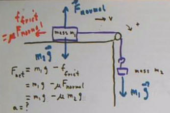
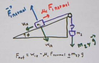
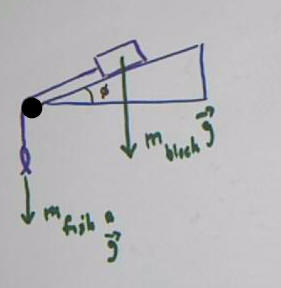
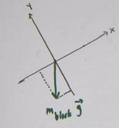
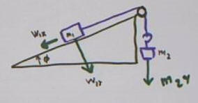
The figure below depicts a block with mass m_block, on an
incline with angle of elevation phi. The mass attached by a light string
over a pulley to a hanging fish of mass m_fish.
The weight vectors m_block g and m_fish g
are depicted by vectors.
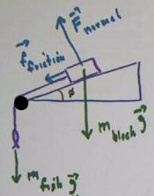
The incline exerts a force f_normal on
the block, in a direction perpendicular to the incline. There is
also a frictional force f_friction between block and incline.
It isn't clear whether the block is moving, so it isn't clear in which
direction to draw the vector for the frictional force. We have chosen
arbitrarily to sketch this vector acting down the incline. If we later
complete the analysis and the frictional force turns out to be up the
incline, our analysis will give us a negative result, indicating that the
vector should be in the direction opposite the indicated direction.
We begin our analysis.
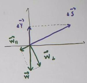
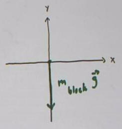
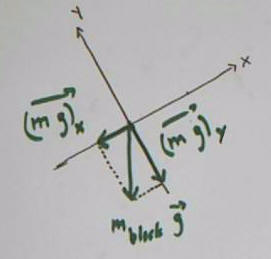
In the figure below the weight vector for the block is
depicted on a coordinate system with the x axis horizontal and the y axis
vertical:
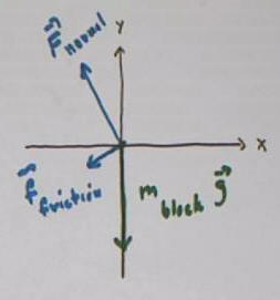
The forces F_normal and f_friction are
added to the diagram so that all the forces acting on the block are
represented:
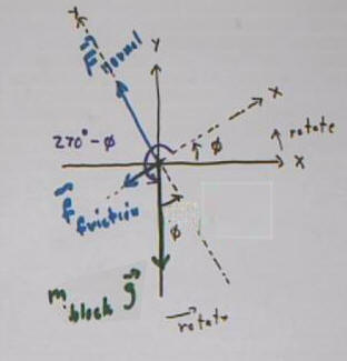
The problem with this coordinate system is that the
motion of the block along the incline will have both x and y components.
We avoid this complication by is rotating the coordinate system so that the
x axis is directed along the incline. Note that this requires a
rotation of the system through angle phi, the original angle of elevation.
This orientation of the axes will also be convenient
for determining the normal force, which is subsequently used in finding the
frictional force. The three forces are depicted on the rotated system:
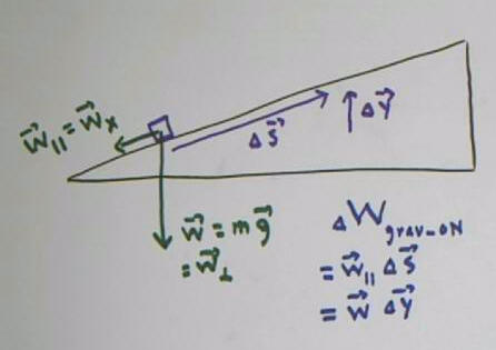
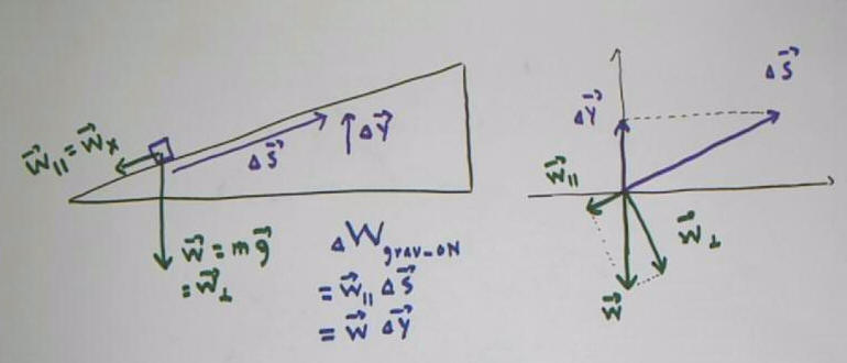
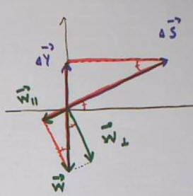
We further analyze the weight of the block:
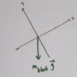
The weight vector is projected onto the x and y axes,
giving us the x and y components (m g)_x and (m g)_y of the
weight.
The gravitational, normal and frictional forces on the
mass can be depicted as below:
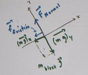
The block has zero acceleration, therefore zero net
force, in the y direction, so the sum of the y forces F_normal and (m
g)_y is zero.
The forces in the x direction are (m g)_x and
f_friction.
If we return to the original situation, we can regard the
fish and block as a system which accelerates at a single rate. We can
choose a positive direction for this system. Given our coordinate system
it would be natural to regard the 'clockwise' direction, in which the mass moves
in the positive x direction and the fish ascends, and the positive direction.
It would also be natural (and more conventional) to regard the
'counterclockwise' direction as positive.
Choosing the 'clockwise' direction, the net force on the
system is
- F_net = -m_fish g - (m g)_x - f_friction
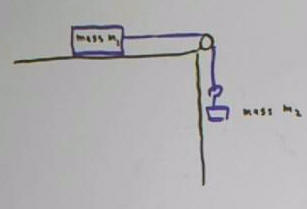
Five systems are depicted below. Sketch each system
and the corresponding force vectors.
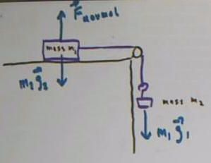
Mass m1 on a level surface, attached by a light string
over a light frictionless pulley to suspended mass m2.
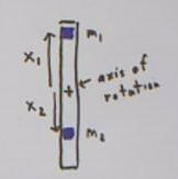
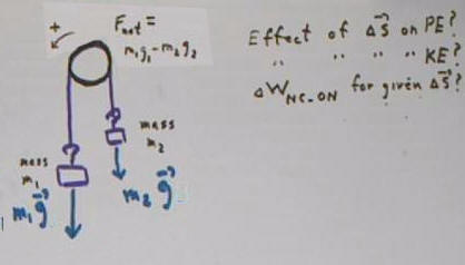
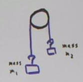
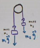
Masses m1 and m2 suspended by a light string over a
light frictionless pulley.
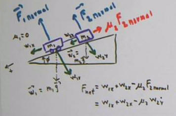
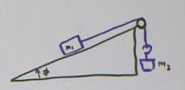
Mass m1 on incline with horizontal attached by light
string over a light frictionless pulley to suspended mass m2. Incline
angle with horizontal is phi.
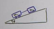
Mass m1 on frictionless wheels attached by light
string to mass m2 sliding on incline. Incline angle with
horizontal is phi.
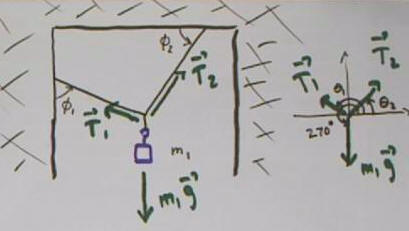
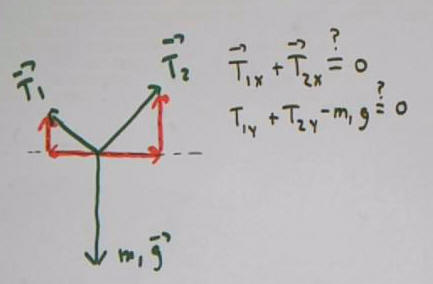
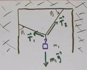
Mass m1 suspended by light strings from rigid wall and
ceiling, first string at angle phi_1 with respect to left wall. second at
angle phi_2 with respect to ceiling.

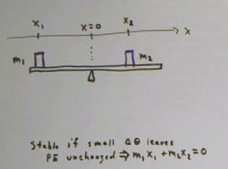
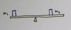
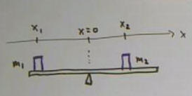
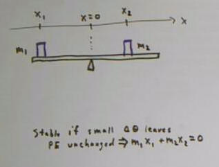
Masses m1 and m2 on light rigid beam balanced at
fulcrum close to mass m2 than to mass m2.
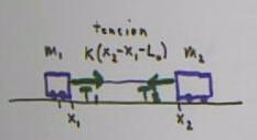
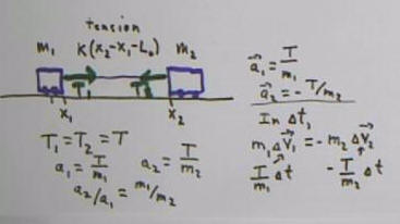
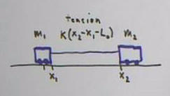
Masses m1 and m2 attached by a light elastic cord,
with cord stretched.
The first of the above systems, with gravitational and forces. Tension forces
may be of interest, but are internal to the system have not been depicted at
this point. Frictional forces have not been included, so each sketch
indicates the frictionless case.
The Atwood system, with gravitational forces. The
pulley would also be supported by an upward force of m1 g1 + m2 g.
Two masses on incline, including weight vectors
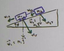
Mass on incline plus suspended mass, gravitational force
on m1 broken into components w_1x and w_1y. The weight is w = m g, and the
components are w1_x = m g cos(theta) and w1_y = m g sin(theta), where theta is
the angle of the weight vector with the positive x axis.
The forces on the mass suspended by three strings.
Each string exerts a tension force, tending to contract it. The string
supporting the mass also exerts a tension force which is not show, but is equal
in magnitude to m1 g.
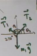
The three tensions can be depicted on a single set of
coordinate axes, with the initial point of each vector at the origin. The
angles theta_1 and theta_2 of the tension vectors T1 and T2 are
indicated. You should be able to express each of these angles in terms of
the given angles phi_1 and phi_2.
The tensions on the two masses connected by the stretched
cord are equal and opposite.