Experiment for this week:
Motion in the Gravitational Field of the Earth.
Check out the link on the 'overviews' button of the main Physics I homepage. You can also access this page from the link below:
The Linked Outline (use the button Overview page or the link provided here) is the document most students find most useful. The Brief Synopsis ... documents are also found useful by many students.
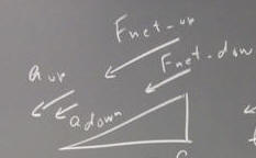
When an object coasts up then down the incline, then if the slope of the incline is greater than the coefficient of friction, the magnitude of its net force when traveling up the incline is greater than the magnitude of the net force when traveling down the incline. The magnitudes of the resulting accelerations are in the same proportion as the magnitudes of the net force, since the acceleration in either case is just the net force divided by the constant mass m.
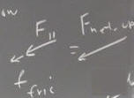
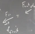
When the object coasts up the incline the frictional force is in the same direction as the component F_parallel of the gravitational force acting down the incline, so the two forces acting together result in a net force of greater magnitude than just that of F_parallel. When the object coasts down the two forces oppose one another, resulting in a net force of lesser magnitude than F_parallel.
Graphically adding the net force when the object coasts up to the net force when it coasts down, we get the difference, which is double the frictional force. Dividing by the mass we get the acceleration vectors, whose difference is double the net force divided by the mass.
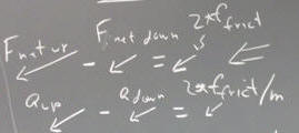
Since the difference in accelerations is 2 * f_friction / m, it follows that f_friction is equal to half the difference in accelerations, multiplied by the mass: f_friction = (a_up - a_down) / 2 * m.

The question was asked concerning the value of the gravitational constant G. That value is 6.67 * 10^-11 N m^2 / kg^2.
Another question was asked about the potential energy of an elastic object. This is often confused with the expression for the force. The expressions for force and potential energy are given below.
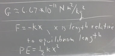
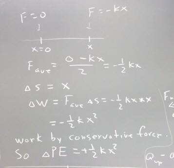
To reason out the connection between these expressions, note that the average force exerted by the tension of an elastic object, between the x = 0 equilibrium position and position x is -1/2 k x, the average of the tension 0 at x = 0 and the tension -kx at position x. Multiplying this average force by the change in position we find that the tension force does work -1/2 k x. Assuming this force to be conservative, the change in PE is therefore equal and opposite to this result. Thus the change in PE is 1/2 k x^2. If the elastic PE is measured relative to the equilibrium position, then PE = 1/2 k x^2.
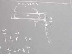
Consider a rotating system consisting of magnets and a strap, with an elastic object exerting a tension for T at the end of the strap. Assume that T is perpendicular to the moment-arm vector r, as depicted below.
The magnitude of the torque exerted on the system is
tau = r * T
(University Physics: The definition of the torque is tau = r X F, where r and F are the moment-arm and the force; in this case the force is T so for this system
tau = r X T.
Applied the depiction in the figure below it is clear that tau is directed 'into' the blackboard.)
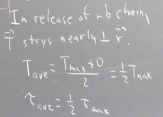
When the system is released from rest the strap will rotated counterclockwise, and the tension force will no longer be perpendicular to the strap. However if the elastic object (e.g., the rubber band) goes slack and loses contact with the strap before it has rotated through more than about 20 degrees, the changing angle will have less than a 10% effect on the torque, and we can to this extent consider the torque to remain nearly constant.
When it goes slack the elastic object will have lost tension and will therefore be exerting 0 force on the system. If the elastic force is a linear function of the object's length, then the average tension is half the maximum tension and the torque is half the maximum torque (max tension and torque occur at the release point).
If the torque is exerted through an angular displacement `dTheta, then it does work
`dW = tau_Ave * `dTheta
and in the ideal case the system should gain an equal amount of rotational kinetic energy. In reality friction and the non-ideal nature of an elastic object will result is somewhat less than the idea kinetic energy.
In our experiment the system then coasts to rest under the influence of friction. We have observed the angle through which the system rotates, and the time required to come to rest. From this information we can reason out the approximate angular acceleration, based on the premise that the angular acceleration alpha of the system is constant (this is not completely so, but it is useful as a first approximation).
The net torque on the system, as it coasts to rest, is just
tau_net = I * alpha.
I is the moment of inertia of the system, which is the sum of the moments of inertia of the strap and the magnets.
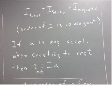
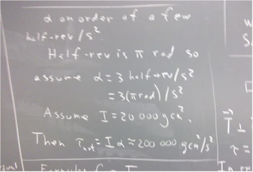
For the system we observed, alpha is generally reported to be a few half-revolutions per second^2. Half a revolution is pi radians. Assume a ball-park value
alpha = 3 half-rev / s^2.
Then since a half-rev is pi radians, we have
alpha = 3 * pi radians / s^2, or 3 pi rad / s^2.
This value is fairly close to 10 rad / s^2.
Typical values of I vary depending on the position of the magnets. I = 20 000 g cm^2 is in the general ballpark. Assuming this value, we find that
tau_net = I * alpha = 200 000 g cm^2 / s^2, very approximately.
Different objects of the same mass can have different moments of inertia (an example being the system we observed; the position of the magnets doesn't affect the mass of the system, but greatly affects its moment of inertia).
It is possible to derive formulas for the moments of inertia of objects having a variety of common shapes. Real objects always have some irregularity in their shape, but their moments of inertia can be approximated to a greater or lesser degree of accuracy by the ideal formulas.
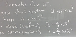
A few of the formulas are given below. The formulas apply to
A thin rod rotating about an axis perpendicular to the rod, through its center.
A hoop rotating about an axis perpendicular to its plane, through its center.
A disk or cylinder rotating about its central axis.
A sphere rotating about an axis through its center.
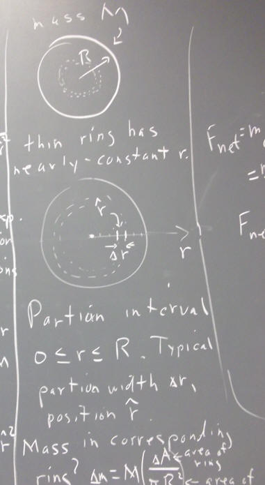
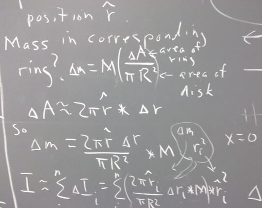
Recall that the moment of inertia of an object is the sum of the m r^2 contributions of all the particles that comprise it.
A little intuitive information:
For a hoop the entire mass M is concentrated at distance R from the center, so every particle is at distance R from the axis. Since r = R for every m r^2 contribution, we can add all the masses before multiplying by r^2. All the masses add up to M, so the moment of inertia is M R^2.
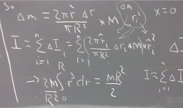
The mass of a disk is distributed all the way from center to outer edge, so almost all points are closer to the center than they would be with a hoop. It turns out that the moment of inertia of the disk is half the moment of inertia of a hoop with the same mass and radius. We get I = 1/2 M R^2.
A sphere is thicker at the axis than at the rim, so its mass is concentrated even closer to the axis than that of a disk. It turns out that its moment of inertia is I = 2/5 M R^2.
For the system consisting of cart and suspended mass, restrained by a rubber band chain:
We ask whether these independent estimates and measurements are consistent.
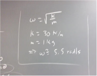
We know that an oscillatory system subject to a linear restoring force F_net = - k x will oscillate with angular frequency omega = sqrt ( k / m ).
(Note: University Physics students have seen that if F_net = - k x, then m a = - k x, so m x '' = - k x, from which we conclude that x = A sin(omega * t + phi), with omega = sqrt( k / m). General College Physics students and Principles of Physics students should simply remember that omega = sqrt(k / m).)
Using k = 30 N / m and m = 1 kg, we get omega = 5.5 rad / s, approximately.
A complete cycle around a circle corresponds to an angular rotation of 2 pi rad / sec, or a little over 6 rad / sec. 5.5 rad / s corresponds to just a little less than a complete cycle in a second. This is consistent with an eyeball estimate of about a cycle per second.
We conclude that our eyeball estimates of mass and period of oscillation are consistent with our measurements.
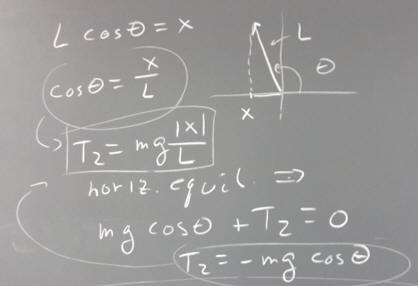
The figure below depicts the forces on a pendulum bob, which is being held in place by a horizontal string. The tension in the pendulum string is designated T_1 and the tension in the horizontal string is T_2.
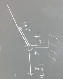
In the figure as drawn the magnitude of the x component of T_1 exceeds T_2, so the net horizontal force is not 0. To represent the horizontal equilibrium, T_2 should be sketched a big longer. The vertical component of T_1 is plausibly equal and opposite to m g.
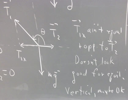
The conditions of equilibrium are that the forces in the x direction add up to zero, and the forces in the y direction add up to zero.
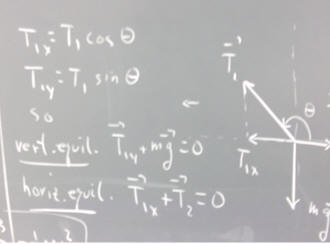
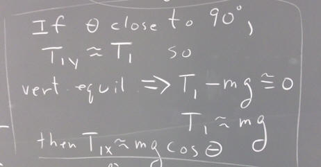
If the angle theta of the pendulum string with the x axis is close to 90 degrees (i.e., if the tension in the string is close to vertical), then the y component of T_1 will have a magnitude which is close to that of T_1. Since the only other vertical force is the downward force of gravity, we conclude that T_1 is close to m g.
It then follows that the x component of T_1 is approximately equal to m g cos(theta).
Now if L is the length of the vector and x the distance of pullback from equilibrium, we see from the figure below that | L cos(theta) | = | x |, so that | cos(theta) | = | x | / L.
Since the T_2 = T_1 | cos(theta) |, and since T_1 = m g, we conclude that
T_2 = m g | x | / L.
If the horizontal string is eliminated, the net force on the pendulum will be equal and opposite to the former tension T_2. Thus the net force on the free pendulum will have magnitude m g | x | / L.
Since the net force is in the direction opposite the displacement of the pendulum from equilibrium, we can write
F_net = - m g x / L,
which is of the form
F = - k x
with
k = m g / L.
Thus a pendulum with a modest swing, for which the angle differs little from vertical, experiences a constant restoring force of form F = - k x, with k = m g / L.
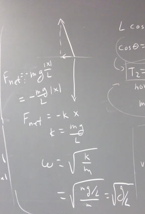
It follows from this that the angular frequency of the pendulum's motion is
omega = sqrt(k / m) = sqrt( (m g / L) / m) = sqrt(g / L).
University Physics Topics
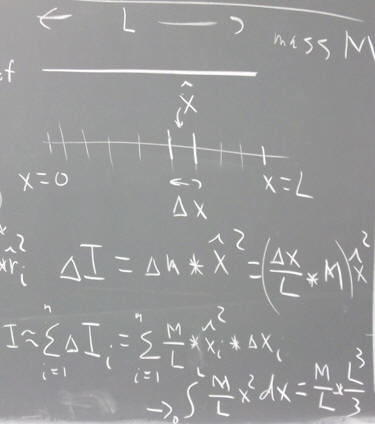
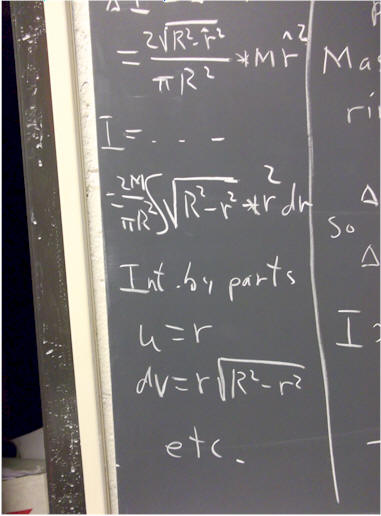
To get the moment of inertia of a thin rod of length L and mass M, pivoted about one end, we can proceed as follows:
We consider the rod to lie along the x axis, between x = 0 and x = L.
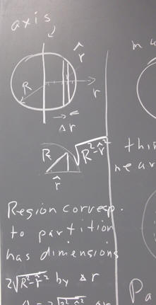
We partition the interval 0 <= x <= L into a number of smaller subintervals.
The length and location of the typical interval will be designated by `dx and x_hat, where x_hat can be regarded as a random point within the interval.
We write the expression for `dI, the contribution of this subinterval to the moment of inertia, as `dm * x_hat ^ 2, where `dm represents the mass in the subinterval. Its distance from the pivot point at x = 0 is taken to be r = x_hat.
Since x_hat is a random point within the interval, there is sure to be some error in letting r = x_hat; however we are going to shrink the intervals toward a limiting length of 0, and when we do this error will disappear.
Our expression is in terms of `dm and x_hat. However that `dm thing just suddenly appeared in our solution, and is as yet unconnected to our assumptions. We must express everything, including `dm, in terms of the known quantities M and L, and the parameters `dx and x_hat. Fortunately it is easy to do so:
`dm represents the mass in an interval of length `dx. This interval is in proportion `dx / L to the length of the interval, so the mass within the subinterval being in the same proportion to the total mass of the rod, we have `dm = (`dx / L) * M.
Thus our contribution `dI to the moment of inertia of the rod is
`dI = `dm * x_hat^2 = (`dx / L * M) * x_hat^2.
If we add up the contributions from all our subintervals, we get the approximate total moment of inertia I. Using the subscript i to denote the numbers of the subintervals making up the partition, we write this approximation as
I = sum( M / L * `dx_i) * xi_hat^2 * `dx_i, i running from 1 to n)
Taking the limiting value of this approximation as the maximum length of the `dx_i approaches zero we get the integral
I = integral( M / L * x^2 dx, x from 0 to L).
This integral is easily evaluated, giving us M / L * L^3 / 3, which we simplify to the form 1/3 M L^2.
We can compare our result 1/3 M L^2 to the formula I = 1/12 M L^2 for the same rod pivoted about its middle. When the rod is pivoted about its end, the typical mass increment is twice as far from the pivot as when it is pivoted about its middle, so m r^2 will be 4 times as great. For the rod pivoted about its middle, then, the moment of inertia is 1/4 as great as when pivoted about an end. 1/4 of (1/3 M L^2) is must 1/12 M L^2.
We could also set up the same integral as before, but with x running from -L/2 to L/2. The integral would then become
integral ( M / L * x^2 dx, x from -L/2 to L/2).
You should perform this integration and confirm that the result is indeed 1/12 M L^2.
cart system: if omega = 10 rad/s^2, k = 30 N / m then m = k / omega^2 = .3 kg.
With 4 dominoes, omega was about 25% greater than with 12.
12 dominoes is about 180 g, 4 dominoes about 70 g.
k = 1 domino / (.6 m) = .2 N / (.6 m), pretty close to 30 N / m.
But the cart is more than 120 g. Probably 200-300 g by itself (may be high).
Lots of consistency checks possible here (energy, forces, frequency, etc.) Great system to study. Wish we could get good pulleys to students (even a bearing wheel with measured I--good experiment in that, of course).
Don't forget buoyant balance. Even slower SHM.
dominoes also interesting, but for the moment exhausted
back to point, 5-count was pretty fast; probably < 1 sec. But that implies higher omega, smaller m.
Based on 400 grams, omega should be about sqrt(30 / .4) rad/sec = 8.6 rad/s. Given uncertainty, not too far off.
Motion detector could work for either buoyant balance (with foam 'flag') or this system.
Photogates with buoyant balance or this system might be useful. Slow enough.
Of course can be set up with air track.
And on inclines.
d: explain to p
When finding the moment of inertia for the strap plus the 2 magnets, do you
add the masses together before m r^2 or do you add the separate moments of
inertia to
equal the I of the strap plus magnets?</p>
<h3>You could add the masses of all magnets whose distances are the same, before
squaring the r. But you couldn't do this with different values of r, because
the r^2 would differ.</h3>
</p>
Also, when measuring the rubber bands, how are we to judge the difference
between suspending the 1 domino and x? I'm confused as to how that plays into
this
experiment or better yet, how to determine it. For example, my chain is 6 rubber
bands long and is 36 cm long when suspending 1 domino. How do I use that
information to determine the average force? </p>
<h3>Subtract 36 cm from the stretched length of the chain. Then multiply by k,
using the rule I gave you to find k.</h3>
ball up and down ramp
do some sample calculations for magnet on strap: I, KE, work by rb
I can't see the flaw right now, and maybe there isn't one. However:
3.9 N cm would be 390 000 g cm^2 / s^2
I for a magnet at the end of the strap would be about 50 g * (15 cm)^2 = 11 000
g cm^2, so your values of I look about right.
Initial angular velocity on the order of 10 rad / s would then result in KE of
about 1/2 * 10 000 g cm^2 * (10 rad/s)^2. Ok, now that's on the order of 500 000
g cm^2 / s^2. I suspect your KE values are 1 order of magnitude lower than your
data would indicate (i.e., looks like you somehow left off a 0; or maybe didn't
multiply half rev / sec by pi to get rad / sec, which would have about the same
effect since pi^2 is close to 10).
Angular velocities are in rad/s; angular vel is squared so you would get g cm^2
* rad^2 / s^2
A radian multiplied by a cm of radius is a cm of arc, so cm * rad = cm and cm^2
* rad^2 = cm^2 (we haven't yet talked about this). So your units are just g cm^2
/ s^2.
<h3>6 cm is not an angular displacement. Angle is measured in radians.
Assuming a 15 cm radius, the angular displacement is 6 cm / (15 cm) = .4
radians.</h3>
Question: `qWhy was it necessary to let the string go slack at the top of the
circle in order to get the desired results?