Notes from Class 1025
Physics
I Quiz 1025
Determine the forces Fx and Fy required to support a 4.9 Newton weight given
that the angle of inclination of the x axis is 20 degrees.
Apply
the problem-solving procedure outlined during the last class to the following
situations:
A pendulum is pulled back
and released.
À A 5 kg simple pendulum of length 4
meters is pulled back .2 meters from its equilibrium position. The pendulum is then released.
A mass m1 rests on a tabletop and is attached to mass
m2 suspended by a string over a pully.
À A 5 kg mass on a table is attached by a
string over a pulley to a suspended mass of 2 kg. The
coefficient of friction between mass and table is .2.
The system is initially moving at .5 m/s in the 'forward and downward' direction,
and it moves 1.5 meters from this point.
À A 5 kg mass on a table is attached by a
string over a pulley to a suspended mass of 2 kg. The
coefficient of friction between mass and table is .2.
The system is initially moving at .5 m/s in the 'forward and downward' direction,
and it moves for 3 seconds starting from this point.
Masses m1 and m2 are suspended from the same string
over a pulley.
À Masses of 4 kg and 5 kg are suspended
by a string over a pulley. Friction exerts a
force equal to .1 times the total weight of the system, which is released from rest and
descends in the direction of the greater mass for 3 meters.
À Masses of 4 kg and 5 kg are suspended
by a string over a pulley. Friction exerts a
force equal to .1 times the total weight of the system, which given a velocity of 2 m/s in
the direction of the 4 kg mass. How far does
the system move before turning around and moving in the opposite direction?
A pumpkin fired from a cannon strikes a moving car
head-on.
À A 10 kg pumpkin moving at 900 mph
(about 400 m/s) collides head-on with a 1500 kg automobile traveling toward it at 30 m/s.
Experiment:
Determine the max
unstretched length of a rubber band.
Using that rubber
band fill the container until the rubber band suspending it exceeds its max
unstretched length by 3 cm.
Suspend the container
from each of the other rubber bands and determine by how much the length of each
differs from its maximum unstretched length.
For angles theta = 15
deg, 30 deg, 45 deg and 60 deg:
Suspend the
container from the original rubber band, and suspend this system from the
other two rubber bands in such a way that
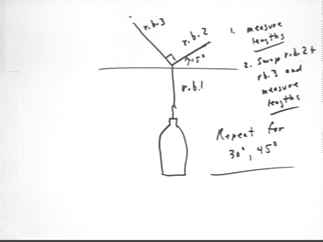
Measure the length
of each of the two rubber bands.
Swap the two
supporting rubber bands and measure the lengths again.
Assume that your
rubber first band stretches by 1 cm for every .7 Newtons of tension.
Determine the weight of the bottle.
e.e., if the
stretch in the first rubber band was 3.0 cm, then the weight of the bottle was
.7 N / cm * 3.0 cm = 2.1 N)
How many Newtons of
force does each of the other two rubber bands exerts per centimeter of
stretch?
e.g., if the
second rubber band had length 2.0 cm when supporting the bottle by itself, and
if the weight of the bottle was 2.1 N, then the stretch of 2.0 cm resulted in
a tension of 2.1 N and the force per cm is 2.1 N / (2.0 cm) = 1.05 N / cm.
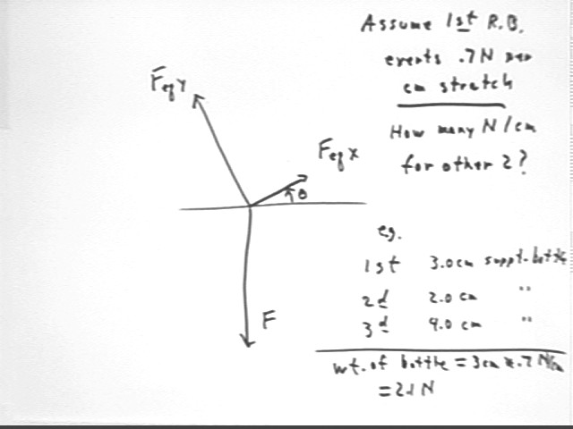
Determine the
tension in each rubber band.
You will use the
number of N / cm for the rubber band and the stretch of that rubber band in
the specific situation you are analyzing.
Find the components
in the directions of the other two rubber bands of the force exerted by the
rubber band which directly supports the bottle.
You will find
the angle of the single supporting rubber band with the positive x axis (in
the direction of the force labeled FeqX in the figure above) and the force of
the single supporting rubber band (represented by F in the figure above) to
find these components.
How well do your
results reconcile with the idea that the tension components of the first
rubber band in the directions of the other two are equal and opposite to the
forces exerted by those two rubber bands?
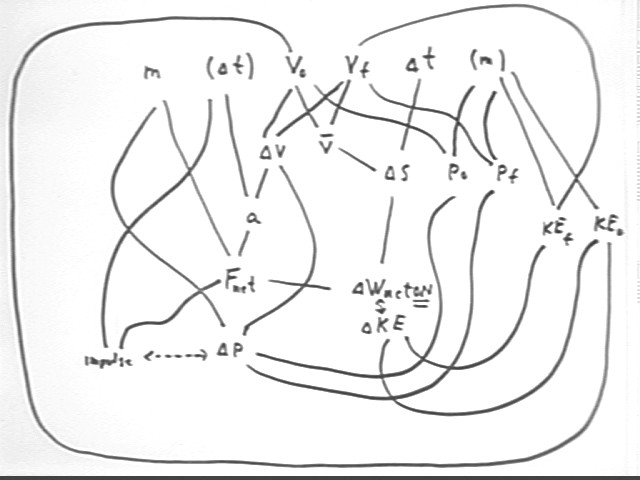
The figure shown below summarizes most of the quantities and relationships
studied so far. Each quantity is a vertex of at least one 'triangular'
relationship.
The arrows between `dWnetON and `dKE, and between impulse and momentum,
indicate that the two quantities connected by an arrow are equal. These
arrows therefore represent the Impulse-Momentum Theorem and hence the Law of
Conservation of Momentum, and the original form of the Work-Energy Theorem.
You should look at each individual quantity, construct every triangle
involving that quantity, write down the basic algebraic relationship between the
quantities and a brief statement of how that relationship represents experience
and common sense, and determine how that relationship allows us to find the
quantity in terms of each of the other two.
You should also review the assigned problems to see how each one 'fits into'
the diagram.
Your goal should be to be able to reconstruct this diagram whenever you need
it.
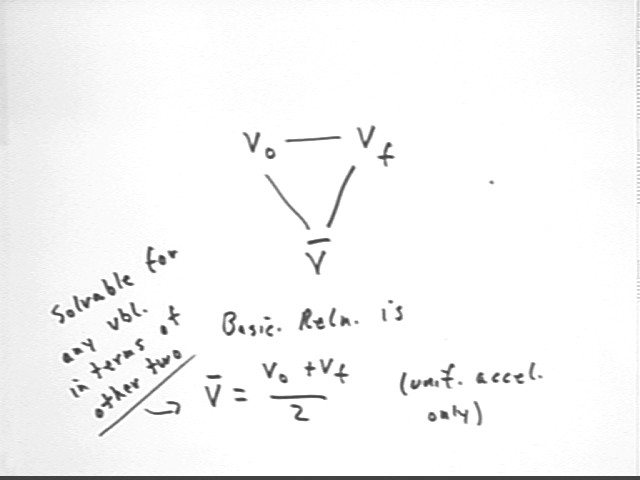
One possible triangle is the one shown
below. This triangle should be among those you construct for each of the
variables v0, vf and `dt.
The defining relationship here is vAve
= (v0 + vf) / 2, as indicated. Note that this relationship applies only to
uniformly accelerated motion.
This relationship is a direct result of
the linearity of the v vs. t graph for unif accel motion.
The relationship is already solved for
vAve; it is easily solved for either v0 or vf. You should do this
solution.
You should do a similar analysis for
every 'triangle' in the larger diagram.
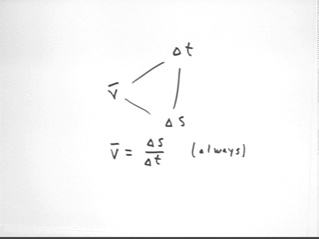
Another triangle involves vAve, `dt and `ds. The defining relationship
here is vAve = `ds / `dt, which holds in every situation.
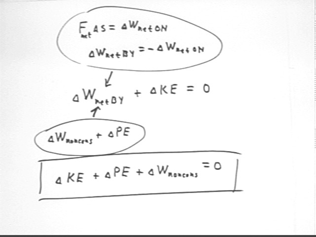
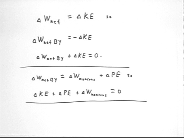
The work-energy theorem as stated in
the diagram says that Fnet `ds = `dWnetON, the work done by the net force ON the
system BY the applied force F. This is natural in the context of the
diagram, where a is the accel of the system and Fnet is the net force exerted ON
the system.
When we change our perspective to that
of the system itself, we want to think in terms of the work done BY the system,
which is the negative of the work done ON the system. We have `dWnetBY = -
`dWnetON, by Newton's Third Law.
From this it follows that `dWnetBy = -`dKE
so that `dKE + `dWnetBY = 0. This is the second form in which we've
seen the Work-Energy Theorem.
If we break the net force exerted by
the system into forces exerted against conservative forces and forces exerted
against nonconservative forces, we express the work done against all
conservative forces as `dPE, the change in the PE of the system. We use `dWnoncons
(sometimes referred to in this context as just W) to represent the work done
against all nonconservative forces. This gives us the third breakdown of
the Work-Energy Theorem:
`dKE + `dPE + `dWnoncons = 0.