Physics I Quiz 1111
Watch the demonstration given at the beginning of class and take careful notes on what you see.
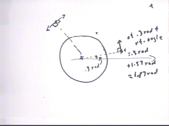
Note that if we wish to achieve a circular orbit at r = 1.5 * Earth radius we must pick a point which lies 50% of an Earth radius beyond the surface. There are several x's marking spots in the figure below. Of these only the one at the .3 radian angle with respect to the positive x axis lies near r = 1.5 Earth radii from the center. We picked this point from all the given points and then estimated the .3 radian angle.
To obtain a circular orbit we must give the satellite and initial velocity which is perpendicular to the radial line, which requires a direction which is perpendicular to the .3 rad direction. A right angle is pi/2 = 1.57 rad (approx) so we add 1.57 rad to the .3 rad angle to get 1.87 rad.
Then starting with initial speed 5000 m/s we ran the simulation. At the 5000 m/s speed the satellite's altitude decreased fairly rapidly and it collided with the planet in the vicinity of the 'top' of the circle.
Increasing the initial speed to 6000 m/s the satellite managed not to fall into the planet but it did 'swing in' closer to the planet, its speed increasing as its 'altitude' decreased. At the point 'opposite' the initial point the orbit did then begin increasing its altitude once more, returning to its initial position.
At 6500 m/s we achieved a nearly circular orbit.
Answer the following questions:
Using the quantities observed what are the KE / kg and the PE / kg for the circular orbit whose radius is 1.5 * Earth radius?
This calculation will be deferred pending the quiz to be given in the next class.
What happens to the orbit if the projectile is started off at .1 radian (about 6 degrees) above, and then at the same angle below, a direction which is perpendicular to the radial direction? How does the motion of the projectile in this case illustrate conservation of energy?
The orbits in both cases became somewhat elliptical, though neither orbit 'crashed' into the planet. It's not possible to achieve a circular orbit starting with velocity in any direction except the perpendicular to the radian line (with any other direction we immediately deviate from the circle).
Suppose we wish to construct a circular orbit of radius 1.7 Earth radii starting at angular position 5 radians. Sketch this situation and specify the initial angular position, initial radius and the direction of the initial velocity. Also show the path of the projectile if we give it an initial velocity which is too low, and also if the initial velocity is too high.
This question will be deferred pending the quiz to be given in the next class.
Is it possible to start off with a velocity which is 'too low' and have the resulting orbit 'miss' the Earth? Explain.
This question will be deferred pending the quiz to be given in the next class.
Is it possible to start off with a velocity which is 'too high' for a circular orbit and not end up forever 'lost in space'? Explain.
This question will be deferred pending the quiz to be given in the next class.
Angular Motion
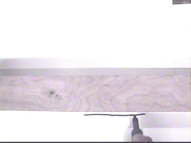
The figure below is a 'top view' of a 'beam' and the cap of a Mr. Sketch marker.
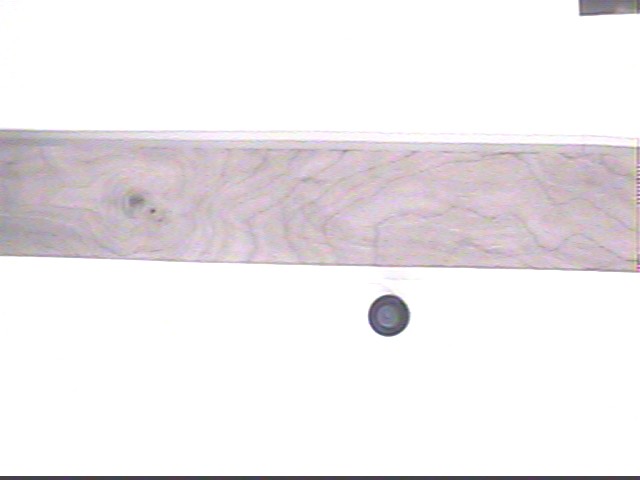
In the next figure the 'beam' is balanced on the marker top and we are marking the direction of the 'beam' by making a line segment parallel to the 'beam'.
Here we have given the beam an impulsive nudge and allowed it to 'coast' to rest. We estimated that approximately 2 seconds were required to come to rest after the brief nudge. We mark the direction of the beam after it has come to rest.
We ask the question 'how fast was the beam moving'.
We concluded that since different parts of the beam were moving at different speeds the only reasonable way we can think of the measure its speed would be to determine the rate at which its direction changes.
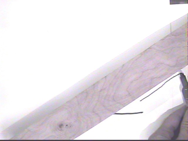
By extending the two line segments marked on the original figure and measuring the resulting angle we easily measure the angle and determine that the direction changed by about 40 degrees.
When working with angular quantities we prefer, for reasons that will soon become apparent, to work with angles in radians. (This will make it much easier to translate angular velocities in radians / sec to linear velocities in m/s for specific locations on the beam).
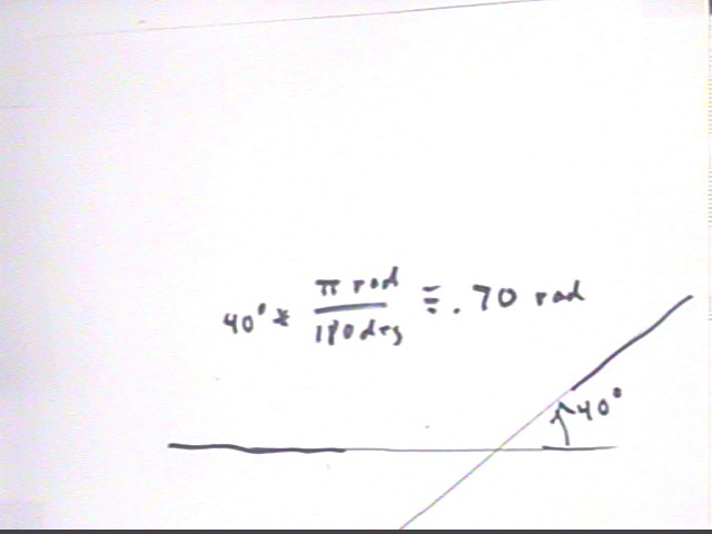
We conclude that the stick moved thru angular displacement .70 radians in 2 seconds. How fast was it moving?
Best answer: 'how fast' is pretty much the rate at which position changes. Position changed by .70 rad during `dt = 2 sec so ave rate of change of position is
ave rate of pos change = change in position / `dt = .70 rad / 2 sec = .35 rad/s.
We call this the angular velocity of the stick. At what average rate was the angular velocity of the stick changing from the instant at which the initial impulse ceased until the instant at which the stick stopped? Assume a constant rate of change of angular velocity.
We can find the answer to this question by graphing angular velocity vs. clock time. We know that the velocity decreases from its initial value to 0 during the 2 second interval, and that the average velocity during this time is .35 rad/s. Since we are assuming a constant rate of change we construct a straight-line graph and indicate the average velocity .35 rad/s at the midpoint of the time interval.
We conclude that to achieve ave vel. .35 rad/s at the midpoint, with final velocity 0 at the end of the time interval, the initial velocity must be .70 rad/s.
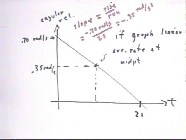
Rate of change of angular velocity with respect to clock time is therefore
Rate of chage of ang vel = change in ang vel / change in clock time = (0 - .70 rad/s) / (2 sec) = -.35 rad / s^2.
There is no difference between the reasoning we are using here and the reasoning we used to analyze uniformly accelerated motion at the beginning of the course. Every bit of that reasoning works for uniformly accelerated angular motion, including the equations of motion, and for University Physics students the use of integrals and derivatives.
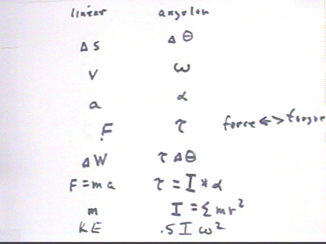
However, whereas before we used v for velocity, a for acceleration and `ds for change in position, we use different symbols for angular velocity, change in angular position and angular acceleration.
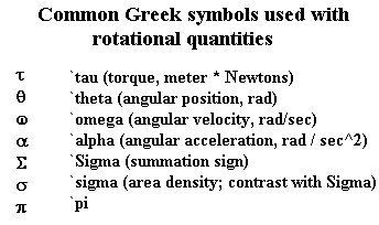
Those symbols are summarized below.
The table below illustrates some of the correspondences between linear and angular motion. The Introductory Problem Sets work through many examples meant to bring out the meanings of these symbols and the reasons for the relationships. Class work will also further illuminate these ideas.
The linear quantities `ds, v and a are replaced in the analysis of angular motion by the Greek symbols `d`theta, omega and alpha.
Force is replaced by torque. We experienced torque in the process of rapidly rotating a meter stick back and forth, then a more massive but shorter 'beam'. Everyone agreed that it required more 'rotational force' to accelerate the meter stick, illustrating that not only the mass but the position of the mass affects the difficulty of achieving angular acceleration.
The quantity analagous to F for linear motion which causes angular acceleration we call 'torque' and symbolize by the Greek letter tau. We will define and experiment with tau in upcoming classes.
The resistance of an object to linear acceleration is mass. Resistance to angular acceleration, as we have seen, depends on both mass and position. We call the quantity 'moment of inertia', symbolized by I, and we note that I = sum(m r^2), where m stands for one of the masses making up the object and r for its distance from the axis of rotation.
Note that the result would be only approximate since the average value of r^2 doesn't occur at exactly the same position as the average value of r (r is linear, r^2 isn't).
Newton's Second Law F = m a therefore becomes tau = I * alpha.
The work done by force F thru displacement `ds is F * `ds; in moving through angular displacement `d`theta under the influence of torque tau the work is tau * `d`theta.
KE, which is .5 m v^2 for linear motion, becomes .5 * omega^2 for rotational motion.
Work and energy for angular motion has the same units, Joules, as work in linear motion. Angular motion has KE just as does linear motion, and one can convert to the other. Any type of PE can convert to angular KE, and angular KE can also be changed by nonconservative forces.
There is also an analog to linear momentum p = m v. This analog is angular momentum I * omega. However this quantity is not in any way equivalent to linear momentum and is not interchangeable with it.
Angular impulse tau `dt and angular momentum I * omega are brand new quantities. Just as is the case for linear momentum, angular momentum is conserved in any closed system. The idea of angular momentum will be further developed in the Introductory Problem Sets as well as in class.