Physics I Quiz 1206
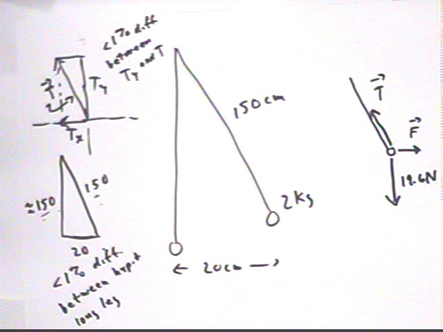
For a simple pendulum of mass 2 kg and length 150 cm how much force is required to hold the pendulum at a position 20 cm from equilibrium?
To hold the pendulum at the 20 cm position requires force F = - Tx =-( -20/150 ) * weight = 20/150 * 19.6 N = 2.6 N.
The figure below review why this is so. The tension vector forms a triangle with the x and y axes which is similar to the triangle formed with the x and y axes by the displaced pendulum (see the two figures at left). At the given displacement we note that there is very little difference (less than 10%) between the 'long side' of either triangle and the hypotenuse so that the y component Ty = m g of the tension is very nearly equal to the tension T, with the x component (by similarity of triangles) very nearly equal to 20/150 * T = 20/150 * weight.
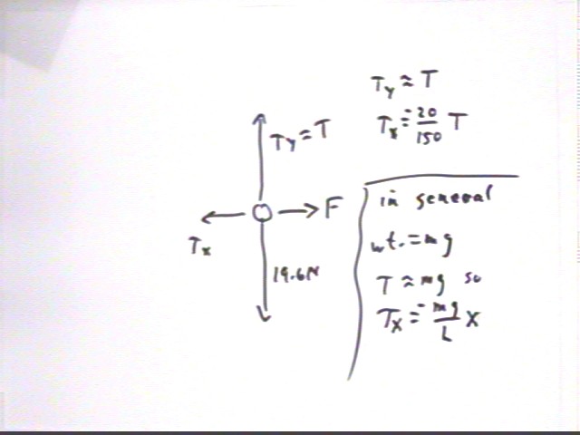
As depicted in the force diagram to the right we have three forces, tension, weight and the force F, holding the mass in equilibrium.
The figure below shows these three forces broken into components, and demonstrates why Tx = - m g / L * x (in the preceding calculations this give us Tx = -(20 / 150) * m g ). We note that the force F must therefore be F = -Tx = m g / L * x.
 *
weight
*
weight
How much work is required to move the pendulum from equilibrium to this position?
Work = ave force * displacement.
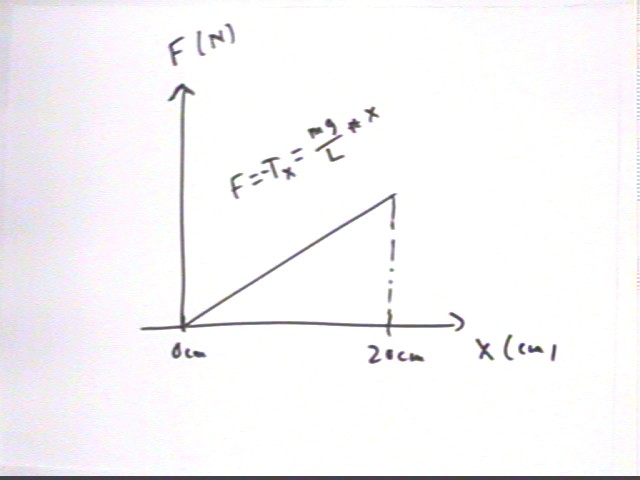
The force at equilibrium is zero and the force at the 20 cm position is 2.6 N. We've just seen that the force is proportional to the pullback distance, meaning that force changes linearly from 0 N to 2.6 N (as depicted in the graph of F vs. x).
Ave force is therefore (0 N + 2.6 N) / 2 = 1.3 N so that work is
work = 1.3 N * .20 m = .26 J.
This work is 'stored' as the PE in the pendulum.
What therefore will be the velocity of the pendulum at equilibrium?
As the pendulum falls back to equilibrium the PE changes to KE.
At equilibrium the 2 kg pendulum will have KE = .26 Joules.
Setting .5 m v^2 = KE we get v = +- sqrt(2 KE / m) = +-sqrt(2 * .26 J / (2 kg) ) = +-sqrt( .26 m^2/s^2) = +-.51 m/s.
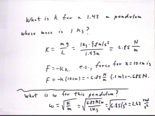
We test our theory for a pendulum of length 143 cm (close to the 150 cm of the example) and mass 1 kg. We will pull this pendulum back 10 cm, release it and stop it at the equilibrium position and determine the range of a bolt sitting freely on top of the pendulum.
For this pendulum we have restoring force F = Tx = - k x with k = m g / L. Don't confuse this with the equilibrant force F of the preceding examples.
We obtain k = 2.85 N / m.
From the force constant k and the mass m = 1 kg of the pendulum we obtain omega = 2.62 rad/s (NOTE that this quantity is incorrectly labeled as 2.62 rad/s^2 in the figure). We note that this differs by about 1% from the 2.59 rad/s observed with the simulation; this difference is most likely the result of the slight damping effect of air resistance and friction in the string supporting the pendulum).
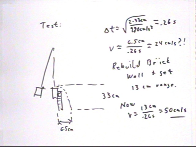
We observe that with a 20 cm pullback the projectile falls 33 cm while traveling 6.5 cm in the horizontal direction. We find that the time required to fall 33 cm is about .26 sec; the 6.5 cm horizontal range tells us that the projectile has horizontal velocity 33 cm / (.26 sec) = 24 cm/s. This is about half of what was observed.
Rechecking the experiment we find that if the pendulum is stopped by a very solid object (the 'brick wall') the projectile travels 13 cm, leading to the revised conclusion that the horiz. velocity is 50 cm/s. This is very consistent with our 51 cm/s theoretical prediction.
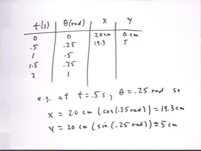
For the given clock times t, give the x and y coordinates of the position of the point on the reference circle. Assume that the center of the reference circle is at (0,0) and the reference circle has radius 20 cm. The angular position of the point is theta = 0 at clock time t = 0 and the angular velocity of the particle is .5 rad / sec:
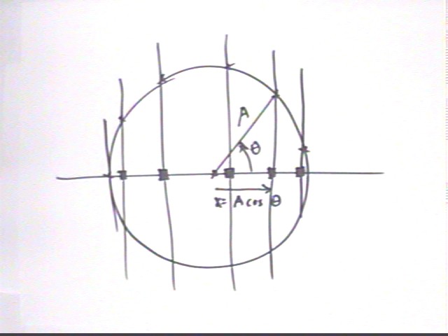
The reference-circle model consists of a circle of radius A and an angular position theta that changes at a constant rate omega. The figure below depicts such a circle with reference-circle points separated by approximately equal increments of the angle theta. The horizontal projection lines for these points intercept the x axis at the positions of the pendulum being modeled. The horizontal-axis intercepts are seen to be x = A cos(theta).
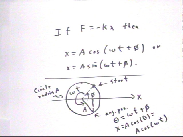
The SHM model applies to an object of mass m subject to a net linear restoring force F = - k x. The motion on the reference circle starts at angular position phi and changes at rate omega, giving us at time t angular position
theta = omega * t + phi
and x coordinate x = A cos(omega t + phi),
which can also be written x = A sin(omega t + phi) for a different value of phi.
The figure at the bottom depicts this situation. Note that the last expression at the bottom of the page, A cos(omega t), should read A cos(ometa t + phi).
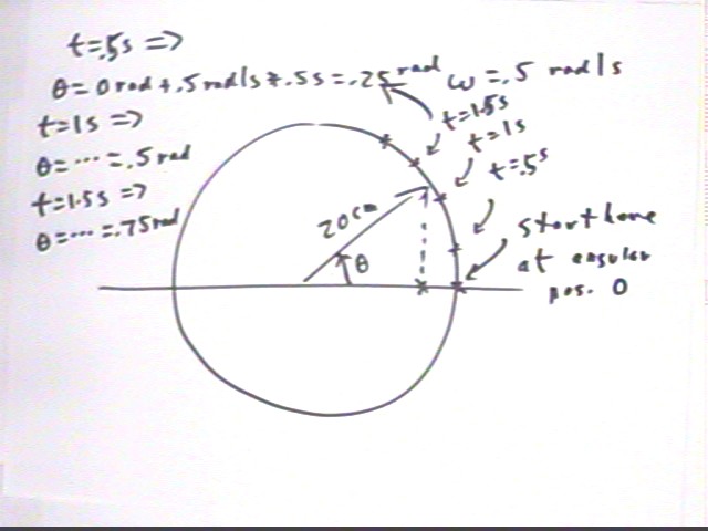
For the given problem the initial angular position is phi = 0 and the angular velocity of the reference point is .5 rad / s. Angular positions, which should be equally spaced but don't look that way in the figure, are shown at t = 0, .5 s, 1 s and 1.5 s. These angular positions are calculated by substituting the clock times t into the expression theta = .5 rad / s * t + 0 rad .
For example for t = .5 s we obtain theta = .5 rad/s * .5 s + 0 rad = .25 rad.
We can make a table of theta vs. t.
At t = 0 our angular displacement is .5 rad / sec * 0 sec; having started at angular position 0 rad so our angular position at t = 0 is
- theta = 0 rad + 0 rad = 0 rad.
x = 20 cm * cos(0 rad) = 20 cm
y = 20 cm * sin(0 rad) = 0 cm
At t = .5s our angular displacement is .5 rad / sec * .5 sec = .25 rad; having started at angular position 0 rad so our angular position at t = .5 s is
- theta = 0 rad + .25 rad = .25 rad.
x = 20 cm * cos(.25 rad) = 19.3 cm
y = 20 cm * sin(.25 rad) = 5 cm.
At t = 1 s our angular displacement is .5 rad / sec * 1 sec; having started at angular position 0 rad so our angular position at t = 0 is
- theta = .5 rad + 0 rad = .5 rad.
x = 20 cm * cos(.5 rad) = 17.6 cm
y = 20 cm * sin(.5 rad) = 9.6 cm
At t = 1.5s our angular displacement is .5 rad / sec * 1.5 sec = .75 rad; having started at angular position 0 rad so our angular position at t = .5 s is
- theta = .75 rad + .25 rad = .25 rad.
x = 20 cm * cos(.75 rad) = 14.6 cm
y = 20 cm * sin(.75 rad) = 13.6 cm.
At t = 2 s we follow similar procedures to obtain x = 10.8 cm and y = 16.8 cm.
The table will look like the one shown below; the x and y columns have not been completely filled in.
For these values of t theta will go from 0 to about 4 rad, roughly 2/3 of the way around the reference circle.
Calculations similar to those done previously give us the coordinates at the given clock times. We obtain the table
| t | x | y |
| 0 | 1 | 0 |
| 2 | 0.540302 | 0.841471 |
| 4 | -0.41615 | 0.909297 |
| 6 | -0.98999 | 0.14112 |
| 8 | -0.65364 | -0.7568 |
For these values of t we find that theta takes values 0, pi/2, pi, 3 pi/2 and 2 pi, with corresponding x and y values as shown in the table below.
| t | x | y |
| 0 | 1 | 0 |
| pi | 0 | 1 |
| 2 pi | -1 | 0 |
| 3 pi | 0 | -1 |
| 4 pi | 1 | 1 |
Sketch a graph of x coordinate vs. clock time t.
The tables yield the graph depicted below for 0 < x < 8.
From the immediately preceding table we see that the x coordinate will go through a complete cycle from x = 1 to 0 to -1 to 0 and back to 1 as t changes from 0 to 4 pi. The y coordinate also goes through a complete cycle from y = 0 to 1 to 0 to -1 and back to 0. So we have a very good idea how to extend the graph.
An extended graph, which goes a bit beyond t = 4 pi, is depicted below.
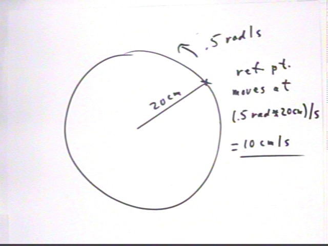
The reference point moves at a constant speed of .5 rad / sec * 20 cm = 10 cm / s. As the particle moves around the reference circle the direction of the velocity vector changes, always remaining perpendicular to the arc of the circle (imagine driving a car around the circle--you are always pointing in the direction tangent to the circle so your velocity is always in the direction tangent to the circle).
We see that motion at .5 rad/s on a reference circle with radius 20 cm implies reference point velocity v = r * omega = 20 cm * .5 rad/s = 10 cm/s.
The velocity vector will therefore always have magnitude 10 cm/s. Its direction will change as we 'drive' the reference point around the circle (just as your direction will change if you drive a car at constant velocity around a circle).
At t = 1.5 s the angular position is .75 rad, as seen previously.
The velocity of the reference point is always tangent to the circle (just as your direction is always tangent to a circle if you drive your vehicle in a circle). The direction tangent to the circle is at every point perpendicular to the radial line. A right angle is pi/2 rad, approx. equal to 1.57 rad. If the motion on the circle is in the positive (i.e., counterclockwise) direction the direction of the velocity vector at t = 1.5 s is therefore rotated 1.57 rad in the positive direction from the radial line:
direction of v at t = 1.5 s: theta = .75 rad + 1.57 rad = 2.32 rad.
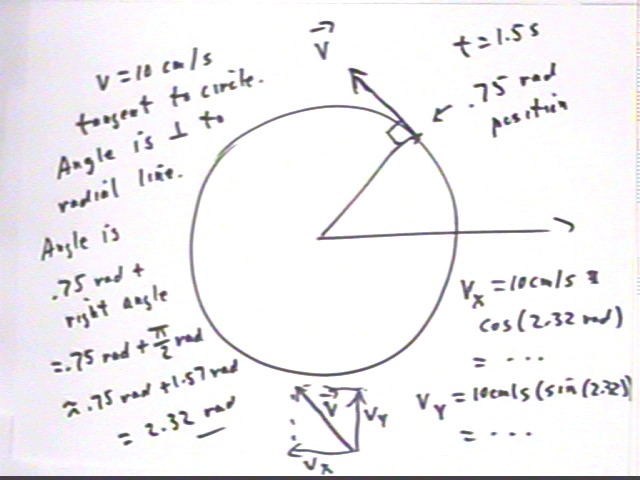
The x and y components of the velocity vector at t = 1.5 are therefore
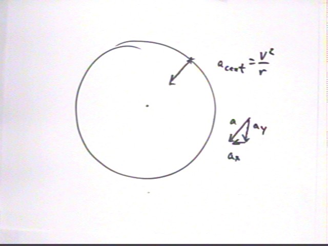
The centripetal acceleration of the reference point is always directed toward the center of the circle.
Answer the following questions relating motion on the reference circle to the motion of a pendulum:
Writeup of Monday's Experiment:
From the projectile behavior determine the velocity of the pendulum at equilibrium for each pullback.
From the length and pullback use energy considerations to figure out the ideal velocity of the pendulum for each pullback.
Figure out the restoring force constant k = m g / L and use it to determine the force exerted at each pullback position.
For each pullback distance determine the average force necessary to pull the pendulum back from equilibrium to that position and use this average force to determine the work done in pulling the pendulum back.
Assuming the work done in pulling the pendulum back is all converted back to KE as the pendulum falls back to equilibrium, find the velocity at equilibrium.