This experiment consists of three parts. Principles of Physics students need do only the first part. The three parts are:
For this experiment you will use four of your calibrated rubber bands, a printed copy of the 1-cm grid, the threaded rod, 4 push pins and eight paper clips.
Rod supported by doubled rubber band, pulled down by two rubber bands
Setup
The setup is illustrated in the figure below. The large square represents the one-foot square piece of plywood, the black line represents the threaded rod, and there are six crude-looking hooks representing the hooks you will make by unbending and re-bending paper clips. The red lines indicate rubber bands. The top rubber band is attached by one hook to the top of the plywood square and by another hook to the approximate center of the rod. We will consider the top of the square to represent the upward direction, so that the rod is considered to be suspended from the top rubber band and its hook.
To rubber band pull down on the rod, to which they are attached by paper clips. These two rubber bands should be parallel to the vertical lines on your grid. The lower hooks are fixed by two push pins, which are not shown, but which stretch the rubber bands to appropriate lengths, as specified later.
The rubber band supporting the rod from the top of the square should in fact consist of 2 rubber bands stretched between the hooks.
The rubber bands will be referred to buy the labels indicated in the figure below. Between the two hooks at the top the rubber band pair stretched between these notes will be referred to as A; the rubber band near the left end of the threaded rod will be referred to as B; and the rubber band to the right of the center of the rod as C.
In your setup rubber band B should be located as close as possible to the left-hand end of the threaded rod. Rubber band C should be located approximately halfway, or a little more, from the supporting hook near the center to the right-hand end of the rod.
Rubber band C should be stretched to a length of 11 cm, while rubber band B should be adjusted so that the rod remains horizontal, parallel to the horizontal grid lines.
Data and Analysis: Mark points, determine forces and positions
Mark points indicating the two ends of each rubber band. Mark for each rubber band the point where its force is applied to the rod; this will be where the hook crosses the rod. Your points will be much like the points on the figure below. The vertical lines indicate the vertical direction of the forces, and the horizontal line represents the rod.
Disassemble the system, sketch the lines indicating the directions of the forces and the rod (as shown in the above figure). Make the measurements necessary to determine the length of each rubber band, and also measure the position on the rod at which each force is applied.
Analyze results:
Determine the magnitude of each force, using the calibration graphs for the rubber bands.
Vertical equilibrium: Determine whether the forces are in vertical equilibrium by adding the forces to obtain the net force, using + signs on upward forces and - signs on downward forces.
Rotational equilibrium: We will regard the position of the central supporting hook to be the fulcrum around which the rod tends to rotate. Determine the distance from this fulcrum to the point of application of the force from rubber band C. This distance is called the moment-arm of net force.
Make an accurate scale-model sketch of the forces acting on the rod, similar to the one below. Locate the points of application of your forces at the appropriate points on the rod. Give the lengths you used in your scale model for the forces, and the distances from the fulcrum to the point of application of each 'downward' force.
The force from rubber band C will tend to rotate the rod in a clockwise direction. This force is therefore considered to produce a clockwise torque, or 'turning force', on the rubber band. A clockwise torque is considered to be negative; clockwise direction is considered to be the negative direction. When the force is exerted in a direction perpendicular to the rod the torque is equal in magnitude to the product of the moment-arm and the force.
Determine the moment arm for the force exerted by rubber band B. This force exerts a counter-clockwise torque, which we will regard as positive.
Ideally the sum of the torques should be zero. Due to experimental uncertainties and to errors in measurement it is highly unlikely that your result will actually give you zero net torque.
Physics 121 students may stop here. Phy 121 students are not required to do the remaining two parts of this experiment.
Simulating Forces and Torques on a Bridge
The figure below represents a bridge extended between supports at its ends, represented by the small triangles, and supporting two arbitrary weights at arbitrary positions (i.e., the weights could be anything, and they could be at any location).
The weights of the objects act downward, as indicated by the red vectors in the figure. The supports at the ends of the bridge hold the bridge up by exerting upward forces, represented by the upward blue vectors.
If the bridge is in equilibrium, then two conditions must hold:
1. The total of the two upward forces will have the same magnitude as the total of the two downward forces. This is the conditional of translational equilibrium. That is, the bridge has no acceleration in either the upward or the downward direction.
2. The bridge has no angular acceleration about any axis. Specifically it doesn't rotate about the left end, it doesn't rotate about the right end, and it doesn't rotate about either of the masses.
Setup
We simulate a bridge with the setup indicated below. Again the system is set up with the plywood square, and with a 1-cm grid on top of the plywood.
The threaded rod will be supported (i.e., prevented from moving toward the bottom of the board) by two push pins, and two stretched rubber bands will apply forces analogous to the gravitational forces on two weights supported by the bridge.
Each rubber band can by stretched to any length between 10 and 11.5 cm. They should however produce unequal forces, representing unequal weights, and one of the rubber bands should be at least twice as far from its end of the rod as the other from its end. Use push pins (now shown) to fix the ends of the hooks and keep the rubber bands stretched.
Note that the length of the threaded rod might be greater than the width of the board. That won't cause a serious problem here--simply place the push pins as far as is easily feasible from the ends and allow a little overlap of the rod at both ends.
Be sure the rubber bands are both 'vertical'--running along the vertical lines of the grid. It should be clear that the push pins are each exerting a force toward the top of the board.
Clearly mark the position of the rod. Keep the lower hooks fixed by their push pins. Then after clearly marking their positions remove the push pins at the ends of the rod.
The two rubber bands will contract and the rod will lie, probably at some nonzero angle with horizontal, on the board. Attach two additional rubber bands, one at or near each end of the rod, with the forces acting at the same positions as the former push pins. Keeping the new rubber bands vertical, return the rod to its former position. This can be accomplished by only one combination of stretches from the new rubber bands--any other combination will fail to duplicate the original position and angle of the rod. Fix the new rubber bands in this configuration, using push pins.
If the rod is back to its original position the original rubber bands are again at the lengths and in the positions they had before you removed the push pins holding the rod. The forces exerted by the new rubber bands have replaced the forces originally exerted by those push pins. The force diagram is as before.
Mark the ends of the rubber bands and note the calibration number of each rubber band. Then disassemble the system.
Analyze your results
The figure below indicates the markings for the ends of the rubber bands, indicated by dots, and the line along which the force of each rubber band acts. The position of the rod is indicated by the horizontal line. The force lines intersect the rod at points A, B, C and D, indicated by x's on the rod.
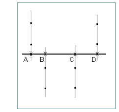
From your markings determine the length of each rubber band and, using the appropriate calibration graphs or functions, find the force in Newtons exerted by each.
Sketch a diagram, to scale, depicting the force vectors acting on the rod. Use a scale of 1 N = 2 cm. Label each force with its magnitude in Newtons, as indicated in the figure. Also label for each force the distance along the rod to its point of application, as measured from the position of the leftmost force.
In the figure shown here the leftmost force would be the 2.4 N force; its distance from itself is 0 and isn't labeled. The 5 cm, 15 cm and 23 cm distances of the other forces from the leftmost force are labeled.
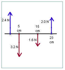
In the figure shown here the sum of all the vertical forces is 2.4 N + 2.0 N - 3.2 N - 1.6 N = 4.4 N - 4.8 N = -.4 N. Is this an accurate depiction of the forces that actually acted on the rod? Why or why not?
In the figure shown here the 1.6 N force produces a clockwise torque about the leftmost force (about position A), a torque of 1.6 N * 15 cm = 24 N cm. Being clockwise this torque is -24 N cm. The 2.0 N force at 23 cm produces a clockwise torque of 2.0 N * 23 cm = 26 N cm. Being clockwise this torque is +26 N cm. What is the net torque produced by the forces shown in this figure? Is this an accurate depiction of torques actually acting on a stationary rod?
Torques Produced by Forces Not at Right Angles to the Rod
Setup and Measurement
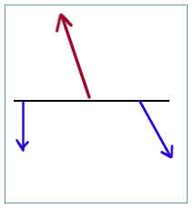
Set up a system as illustrated below. As before the 'top' rubber band will in fact consist of two rubber bands. The leftmost rubber band will remain vertical, while the rightmost rubber band will be oriented at a significant angle with vertical (at least 30 degrees). The rightmost rubber band will be stretched to a length of at least 11 cm, and its point of attachment will be at least a few centimeters closer to that of the center rubber band than will the leftmost rubber band.
Mark the ends of the rubber bands, the points at which the forces are exerted on the central axis of the rod, and the position of the central axis of the rod.
Measure the lengths of the rubber bands. Measure also the angle from horizontal of each of the non-vertical rubber bands.
Analysis
Using your calibration graphs or functions find the magnitude of the force exerted by each rubber band.
Sketch a force diagram showing the forces acting on the rubber bands, using a scale of 1 N = 2 cm. Label the positions at which the forces act on the rod, the magnitude in Newtons of each force and the angle of each force as measured counterclockwise from the positive x axis (assume that the x axis is directed toward the right).
Find the components of each force:
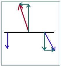
The torque produced by a force acting on the rod is produced by only the component perpendicular to the rod. The component parallel to the rod has no rotational effect.