"
Class Notes Physics I, 9/23/98
Forces, Work, Energy
Rubber Band: Force
vs. Stretch graph and Work
Rail Sliding across Floor: Work and
Energy
From a graph of rubber band force vs. stretch we can determine the work required to
achieve any given stretch. We can either approximate the work over a series of small
distance increments or (University Physics students only) we can use calculus to integrate
a function which fits our force vs. stretch data. The stretched rubber band has the
potential to do work on the rail, and we refer to this as the potential energy of the
rubber band.
The rail is projected from the rubber band with a kinetic energy that accounts for
most of the potential energy of the stretched rubber band. As a rail slides across
the floor its kinetic energy decreases; we can think of the lost energy as the energy
required to do the work of sliding.
As the rubber band contracts it cools and therefore loses thermal energy, leaving
it less energy to accelerate the rail.
As the rail slides down a constant-velocity slope, where the net force must by
Newton's First Law be zero, the frictional force balances the component of the weight in
the direction of the ramp. The net work done on or by the rail is therefore zero.
Questions:
- What would a graph of potential energy vs. stretch look like for the rubber band?
- What would a graph of kinetic energy vs. distance look like for the rail sliding
across the floor? Would the graph be linear or would it curve? If it would
curve, in what direction would it curve?
- How is it that we can regard the force of gravity as equivalent to two forces, one
parallel and one perpendicular to the ramp?
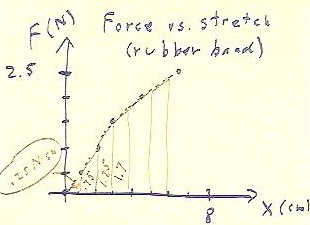
The graph below shows the force to stretch a rubber
band versus the stretch.
- The data points, indicated by blue dots, are (1 cm, 0.5 N), (2 cm, 1.0 N), (3 cm, 1.5
N), (4.5 cm, 2.0 Newtons), (6.5 cm, 2.5 Newtons).
Since the work done over any 1-cm distance increment is
equal to the average force multiplied by that distance,
we can calculate the approximate work done during each increment by
calculating the areas of the trapezoids indicated in the
figure, for which average heights represent approximate average
forces and widths represent the distances over
which these average forces apply.
- Since the data is not perfectly linear we use an approximate
curve to estimate the forces involved.
- Estimates made from this graph indicate work contributions of .25,
.75, 1.25, 1.7, and 1.95 N cm for the first six intervals shown.
- These work contributions (except for the last, which was inadvertently left off) are
indicated on the graph below.
- Note that these contributions should have been circled, since they represent areas; the
circles were left off for readability.
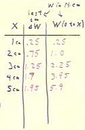
The table in the figure below shows the stretches x, the work
contribution from the cm of stretch preceding x (e.g., when x =
3 cm, the work contribution is for the interval from x = 2 cm to x = 3 cm), and the total
work from the unstretched position (x = 0) to stretch x.
- This last total is found by adding the work
contributions for all 1-cm increments preceding x.
We see that the total work done in stretching the rubber band from x
= 0 to x = 5 cm is approximately 5.9 N cm.
http://youtu.be/GNUobGNlsqI
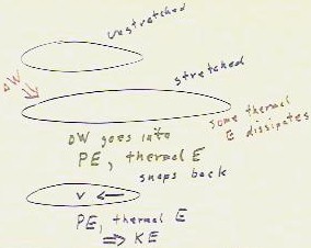
The energy situation is depicted in the figure below.
- We do work `dW on the unstretched rubber band,
resulting in a stretched rubber band (the work contribution `dW is indicated in red).
- This work contribution goes into potential energy and into thermal
energy.
- The thermal energy can be easily detected by holding an unstretched
(and clean) rubber band against your upper lip, just below your nose.
- If you suddenly stretch the rubber band, you will feel the rubber band
become warm. If you then suddenly return the rubber band
to its unstretched state, you will feel it cool off.
When the rubber band is stretched and warms up, it
immediately begins losing thermal energy to the air around it,
as warm objects do.
- So some of the work done in stretching the rubber band
is dissipated.
- Nearly all of the remainder of the energy will be
present in the form of mechanical (and thermal) potential energy.
- When the rubber band is released it snaps back
(if attached to a rail or other object, it accelerates that object), and attains
kinetic energy.
- Since it cools off, it loses thermal energy, which is
also manifested as increased kinetic energy.
The result is that most, but not all of the work put
into the system is released as kinetic energy.
Rail Sliding across Floor
http://youtu.be/VdQsBeKNS_8
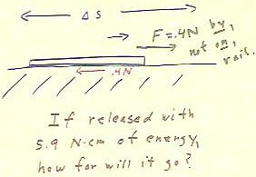
As seen earlier when the rail slides across the floor it must exert a
force of .4 Newtons in reaction to the .4 Newton
frictional force that resists its motion.
- It should be noted that the .4 N force, exerted to the
right in the figure below, is a force exerted by and not on the
rail.
- The net force on the rail is the .4 Newton frictional force.
- This net force results in the negative acceleration,
which eventually stops the rail.
If we assume the ideal case in which no energy is dissipated
in the rubber band, then a rail accelerated by a rubber band stretched
5 cm from its unstretched length should attain 5.9 N cm of
kinetic energy.
- When it stops its
kinetic energy will of course be 0, so its change
in kinetic energy will be -5.9 N cm.
- Since this change is the result of
the .4 N force exerted by friction, it must be equal
to the work done by friction.
- This work is -.4 N * `ds (the
force is exerted in the direction opposite to the displacement so the product is
negative), and is equal and opposite to the work done by
the rail, which is clearly .4 N * `ds.
We can therefore easily find how far the rail should go.
- Its displacement should be `ds, where .4 N * `ds = 5.9 N cm.
- We easily find `ds = 14.75 cm.
From a set of observations of rubber band force vs. stretch, we should
be able to use this process to predict how far the rail should travel for
each pullback and compare our predictions with
the set of observations of rail distance vs. pullback to
see what evidence we have that energy is in fact conserved in
this situation.
http://youtu.be/jANBVBrtQlw
We can also determine how fast the 'rail' should be traveling
if it does in fact gain KE equal to the PE of the stretched
rubber band.
- We have seen that the potential
energy of the stretched rubber band should be approximately 5.9
Newton cm.
- We note that this is not the
standard unit of energy. That unit is the Joule, equal
to a Newton meter.
- Since one cm is 1/100 of a meter,
it makes sense that a N cm should be 1/100 of a N m, so
that the 5.9 Newton cm energy will be equal to .059 N m,
or a .059 Joule energy.
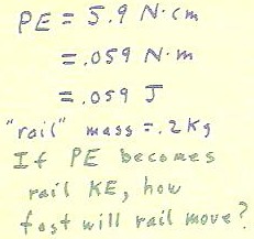
Given that the rail mass is .2 kg (which can be
determined using a pan balance, or by using the weight of the rail to deflect a pendulum
of known length and mass, or by hanging it from a spring balance), we can easily determine
its velocity when its kinetic energy is .059
Joules.
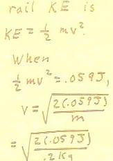
- Since kinetic energy is
.5 m v^2, we simply set this expression equal to the .059 Joules and
solve for v.
- The solution is straightforward
and is shown in the figure below.
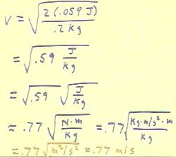
In solving for the velocity we have to treat the units very
carefully.
No calculation in
this course is acceptable if quantities which have units are expressed without units, and if careful and documented
unit calculations do not accompany all work.
The figure below shows the complete calculation.
We note that the numerical calculation is straightforward, and that
the quantity under the square root sign becomes .59 J / kg.
- We separate this expression into
the expression `sqrt(.59) * `sqrt(J / kg), compute the numerical
square root and replace the J by N m.
- We then note that a Newton,
defined as the force which accelerates a kg at 1 meter/second ^ 2, has units
of F = ma, or kg m / s^2.
- So the unit for
the calculation becomes `sqrt( (Kg m / s^2 * m) / Kg).
- This simplifies to `sqrt(m^2
/ s^2), then to m / s, so we obtain the final result .77
meter/second.
Rail sliding down a smooth ramp
We now look at a rail sliding along a smooth ramp whose slope is adjusted so
that the rail neither speed up nor slows down.
http://youtu.be/ABr7Z70XsFk
http://youtu.be/U_I8nqcHIvE
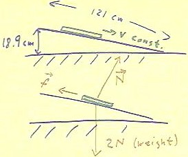
By adjusting the slope of a smooth ramp, we can find
a slope on which the rail slides very slowly down
the ramp at very nearly constant velocity.
- Having found this slope we measure
the rise of the ramp and its length.
- For this information we can easily
find the slope of the ramp.
Newton's first law tells us that this constant-velocity
situation (as any constant-velocity situation) arises because the net
force on the rail is zero.
- How can the net force the zero in this situation?
We can list the forces acting on the rail.
- We have the force exerted by the mutual gravitational attraction of the
masses of the rail and the Earth.
- Since we observe that the rail would accelerate downward at 9.8
m/second ^ 2 under the influence of this force, we easily find that its .2
kg mass experiences a gravitational force of 1.96 Newtons, which
we round off to 2 Newtons.
- This force is called the weight of the object.
- In the figure below this force is depicted as acting straight downward.
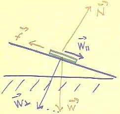
We also have a frictional force, labeled f in the figure below, which
acts opposite to the direction of motion.
And we finally have the force exerted by the incline to support
the rail.
- This force is called a normal force, indicated by N with
a small arrow over the top of it (which shows is that this N represents a
vector force and not the Newton unit).
- This normal force acts in a direction perpendicular to the incline.
We note that three forces in these directions can indeed be in
balance, or in equilibrium.
- The weight and
the normal force will have a net effect toward the right,
perhaps a little bit upward or a little bit downward depending
on the relative strengths of these forces, and might well and up equal
and opposite to the frictional force f.
This woud constitute equilibrium.
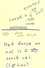
We digress by looking again at a rail moving along the floor at
constant velocity.
- This time the .4 N force to the right is
exerted on the rail by some external force, perhaps by us pulling it
along.
- In this situation the force on the rail is 0
(the normal force of the floor pushing upward on the rail exactly
balances the gravitational force pulling down, and the .4
Newton force of friction opposing motion is exactly balanced
by the .4 N force exerted on the rail).
- Newton's first law assures us that this zero
net force results in motion with constant velocity.
http://youtu.be/NIzGz_l3IG8
Without yet going into the trigonometric details of vector
analysis, we make a plausibility argument showing how we might
see that the net force is equal to 0.
- The forces Wparallel and Wperpendicular labeled in
purple in the figure below are to be regarded as completely equivalent to
the weight W.
- We should understand that if we pulled on an object with two
such forces in the indicated directions, with the force
indicated by the longer arrow being proportionately stronger,
they might have an effect identical to that of the downward force of gravity.
- In that case the force of gravity could be replaced by
these two forces.
- The two forces replacing gravity could be oriented so that one
acts parallel to the incline while the other acts perpendicular to
the incline.
- It is then conceivable that the force acting parallel to the incline
could be equal and opposite to the frictional force, and
that the normal force could arise naturally to exactly balance the
weight component perpendicular to the ramp.
What happens when the ramp is gradually raised is that the frictional
force resisting the motion of the object down the incline keeps increasing
in response to the growing weight component parallel to
the ramp.
- This continues until the frictional force can
no longer exceed that weight component, at which time all
forces are in balance and any small velocity given
the rail will be maintained.
In subsequent lectures and experiments we will learn what we need to analyze these
forces and the energy changes associated with them.
http://youtu.be/OSgZnsvz1U8
"
