"
Class Notes Physics I, 11/18/98
Cantilevered Beam: Statics and Dynamics
http://youtu.be/UhVcSjfw2NY
http://youtu.be/k2QpjCylUCQ
The quiz problem concerned a uniform beam of given length constrained to rotate about
one of its ends.
- The beam was to be allowed to fall from rest as it rotates around the fixed end.
- We were to determine the kinetic energy and angular velocity of the beam at the instant
its center of mass had fallen a given distance.
- We were also to determine the torque and angular acceleration on the freely falling beam
at the instant it makes a given angle with the horizontal direction.
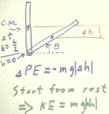
The figure below depicts the beam in two positions.
- The first is its original vertical position, where its center of mass is at altitude L/2
(i.e., half the length of the beam) with respect to its fixed end, where we set h = 0.
- The second is its position after it has fallen a distance `dh. We also indicate the
angle `theta of the beam with respect to the horizontal direction.
As the beam falls, its center of mass also descends.
- Since the entire weight of the beam can be considered to be concentrated at the center
of mass, we see that when the center of mass has fallen distance |`dh|, its potential
energy will have decreased by - m g `dh.
It follows that if the beam starts from rest and if no dissipative or other external
forces other than gravity act on it, it will have attained kinetic energy equal to the
potential energy lost. In that case its kinetic energy will be KE = m g |`dh |.
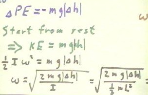
The kinetic energy of a rotating object is 1/2 I `omega^2.
- This kinetic energy will be equal to m g |`dh |, so we have the equation 1/2 I `omega^2
= m g |`dh |.
- We solve this equation to determine `omega, with the results shown below.
- The final form of the expression for `omega, which is not shown below, is
- `omega = `sqrt( 6 h |`dh | ) / L.
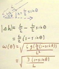
We might wish to determine the angular velocity of the object as a function of the
angle `theta as measured from the horizontal direction.
- If the angle of the beam with horizontal is `theta, then the altitude of the center of
mass will be h = L/2 sin(`theta), as indicated by the triangle in the figure below.
- In this case we see that the altitude has decreased from its original L/2 to L/2
sin(`theta), so that |`dh | = L/2 - L/2 sin(`theta) = L/2 (1-sin(`theta).
- Substituting this expression for `|dh | into the equation `omega = `sqrt(6 g |`dh | ) /
L, we obtain the angular velocity as a function of angle:
- `omega(`theta) = `sqrt[ 3 g (1 - sin(`theta)) / L ].
http://youtu.be/8zwbL9iFoVg
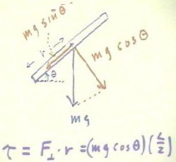
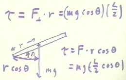
To determine the torque on the beam when its angular position is `theta, we can break
the weight mg into components parallel and perpendicular to the beam.
- We easily find that the component parallel to the beam is m g sin(`theta) and the
component perpendicular to the beam is m g cos(`theta).
- From direct experience we know that the component of the force parallel to the beam has
no effect on rotation, so the torque of this force is just Fperpendicular * r =
mg cos(`theta) * (L/2), where r is a fairly standard notation for the length of the moment
arm.
We can also determine the torque by using the effective moment arm, which is the
perpendicular distance from the axis of rotation to the line of action of the force.
- If the force mg acts at distance r from the axis of rotation, as measured along the beam
which is at angle `theta with respect to horizontal, then since the line of action of the
force mg is vertical, the component of the moment arm perpendicular to this line of action
is its horizontal component r cos(`theta).
- The torque is thus F = r cos(`theta); since r = L/2 in this case we have
- torque = `tau = m g (L/2 cos(`theta)).
We note that this expression for
the torque is identical to the one previously found. The only difference is in the
way we look at the situation (i.e., focusing on either the components of the force or on
the line of action of the force).
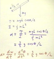
The resulting acceleration on the system can now be found from Newton's Second Law, in
its rotational form `alpha = `tau / I.
- The moment of inertia of a uniform beam of mass m and length L, rotated about one of its
ends, is I = 1/3 m L^2.
- We thus obtain the angular acceleration as shown below, with the final result that
angular acceleration is 3/2 g cos(`theta) / L.
- Calculus-literate students note: Since the instantaneous angular acceleration `alpha is
the first time derivative of the angular velocity `omega, which in turn is the first time
derivative of the angular position `theta, we see that d^2 `theta / dt^2 = 3/2 g
cos(`theta) / L. This is a differential equation from which we can find the angle `theta
as a function of time t. You should solve this equation.
We also note that the 1/L proportionality of acceleration and beam length can be tested
by allowing a variety of beams of different lengths to fall, and determining the time
required for them to fall.
- Knowing that average acceleration
will be inversely proportional to the square of the time required for the fall, and that
average acceleration should be inversely proportional to the length of the beam, we can
analyze our results to determine if our data are consistent with these assumptions.
- You should design an experiment to
test these assumptions.
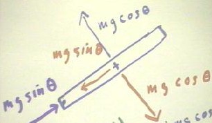
We now consider the equilibrium of the the forces acting on the beam. Recall that the
weight components parallel and perpendicular to the beam were previously found to be mg
sin(`theta) and mg cos(`theta), respectively.
Suppose that we wish to keep the beam from rotating by applying the least possible
force at the beam's center of mass.
- It should be clear that we can achieve rotational equilibrium by with a force m g
cos(`theta) at the center of mass, with the direction of the force opposite to that of the
weight component m g cos(`theta).
- (We could prevent rotation by applying a force at the center of mass but in a different
direction, but since only the component perpendicular to the beam and therefore parallel
to the y axis will have any effect on rotation, such a force would have to be larger than
the m g cos(`theta) necessary to balance the torque resulting from the weight.)
- Not only would this force result in a net torque of zero, it would also ensure that the
system remain in equilibrium in the y direction. No other force would be necessary to
ensure y equilibrium.
We also have equilibrium in the x direction, which tells us about the force on the axle
about which the beam pivots..
- We therefore need a force to balance the m g sin(`theta) weight component in the x
direction.
- In the situation we are studying this force will be supplied by the axle at the pivot
point, and will be equal to m g sin(`theta) in the direction opposite to that of the
weight component in the x direction.
- We therefore see that by applying a force m g cos(`theta) in the x direction, the axel
must exert a force m g sin(`theta), and that this force is only in the direction of the
beam; the axle exerts no force perpendicular to the beam.
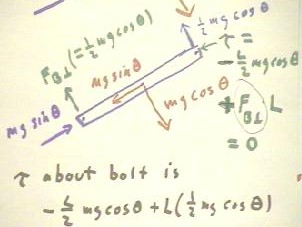
Suppose that we now wish to apply a force at the free end of the beam, in the most
advantageous direction, in order to prevent the beam from rotating.
- Since the free end is twice as far from the axis of rotation as the center of mass, we
will prevent rotation by applying at this end a force equal to half the perpendicular mass
component m g cos(`theta).
- The force will be directed perpendicular to the beam and will exert torque 1/2 m g
cos(`theta) * L (the torque of this force is in the counterclockwise direction and is
therefore positive).
- The weight component m g cos(`theta) will also exert a torque, equal to -m g cos(`theta)
* (L/2) (this torque is in the clockwise direction and is hence negative).
- The torque about the axle will therefore be sum(F*r) = -L/2 mg cos(`theta) + L (1/2 m g
cos(`theta)) = 0.
Torque will balance but forces in the y direction will not.
- Since we have y forces -m g cos(`theta) and 1/2 m g cos(`theta) (assuming a y direction
which is up and to the left), we require another y force 1/2 m g cos(`theta) to achieve y
equilibrium.
- This force will be exerted by the bolt.
- As before, the bolt must also exert a force m g sin(`theta) in parallel to the beam.
This force is necessary to balance the weight component m g sin(`theta).
http://youtu.be/3PJlbvwESu8
http://youtu.be/KMBRuFeyocs
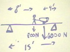
Now consider a person weighing
800 N wheeling a 6000 N load of concrete across a bridge.
- We will assume that the bridge is strong but of insignificant mass.
- Assume that the individual is at a point 8 feet from the left pier supporting the
bridge, and that the load is perfectly balanced at a point 4 feet from the right
supporting pier.
- Assume also a 15 foot distance between piers.
We wish to determine the forces exerted by both piers to support the total load. We
will do so by using first the fact
that the pier is not rotating about the left-hand support.
We begin by determining all the torques about the left-hand pier.
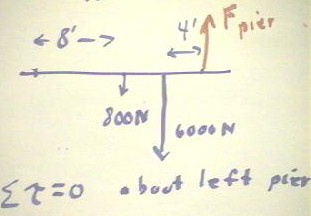
- The 800 Newton and 6000 Newton forces tend to rotate the system about the left-hand pier
in the clockwise direction; the associated torques are therefore -800 N * 8 ft and -6000 N
* 11 ft.
- (You might have noticed that we are mixing Newtons and feet in this example. To be
perfectly consistent with units we should probably change our feet to meters or,
alternatively, Newtons to pounds; however as we will see in this case it really doesn't
matter, has long as we keep our force units and our distance units the same).
- The torques are -6400 ft N and -66000 ft N.
Clearly, since the bridge presumably doesn't rotate in response to these torques, there
is at least one other force acting to produce a torque in the positive direction. The sum
of all torques on any system in equilibrium has to be 0.
The one obvious force that we have ignored to this point is the force exerted by the
right-hand pier.
- This force is exerted at a point 15 feet from the left-hand pier.
- We have implicitly assumed without stating it that the bridge is horizontal and that the
piers exert only vertical forces to support the bridge.
- It follows that the force Fpier of the pier must be perpendicular to the
bridge, and hence to the moment arm from the left-hand pier.
- The torque exerted by this force is thus Fpier * 15 ft..
If no other forces act on the system (and no other forces are necessary to fulfill the
conditions of the problem), then we express the fact that the sum of the torques is zero by the equation
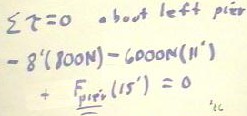
- -8 ft * 800 N - 11 ft * 6000 N + Fpier * 15 ft = 0.
This equation is easily solved, with a result that Fpier = 72400 / 15 N =
4800 N (approx).
We could easily proceed to find the force exerted by the left-hand pier.
- The total vertical force in this equilibrium situation is -800 N - 6000 N + 4800 N + Fpier1
= -2000 N + Fpier1 = 0, where Fpier1 is the force exerted by the
left-hand pier.
- It follows that Fpier1 = 2000 N.
- The commonsense of the situation is that there are two downward forces totaling 6800 N
and one upward force of approximately 4800 N, so to attain equilibrium we need another
upward force of 2000 N.
- We obtain this force from the first pier.
If we calculate the total torque about the right-hand pier, using the given forces and
the accurate force (near 2000 N) obtained for the second pier, we see that the torques add
up to zero (you should do this calculation).
- The torques must add up to zero if we are to have an equilibrium situation, and the fact
that they do provides a check of our original result.
http://youtu.be/6ev5SCg4Pkw
"
