In a series circuit with DC generator, resistor and capacitor, what happens to the voltage on the initially uncharged capacitor when the generator is cranked at a constant rate?
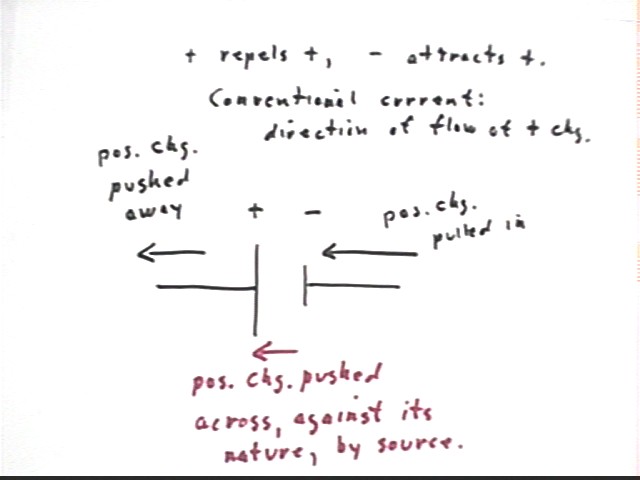
Answer: The source has a positive and a negative terminal. The positive terminal tends to push positive charge away, so if this is the only source of potential difference the direction of the current is away from the positive, and toward the negative terminals. Note that within the source positive charge would be 'pushed' across from the negative (which ordinarily tends to attract positive charge) to the positive terminal (which normally repels positive charge). This goes against the nature of positive charge, and in the process of moving positive charge from the negative to the positive terminal work would be required.
In an actual circuit with conducting wires it is usually electrons which carry the charge, and electrons move in the direction opposite to that shown. Movement of negative charges in one direction is equivalent to movement of positive charges in the opposite direction.
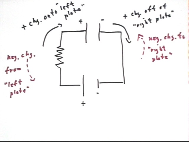
If there is an initially uncharged capacitor in the circuit, and possibly but not necessarily a resistor, the the effect of the source is to carry positive charge to the plate nearer the positive terminal of the source and/or to 'pull' negative charge from that plate, and to 'pull' positive charge from the other plate and to 'push' negative charge toward that plate.
Does the voltage across the capacitor reinforce or oppose the voltage created by the generator?
Answer: As seen in the previous answer the increasing positive charge on one plate, and the increasingly negative charge on the other, each 'push' current in the direction opposite to that of the terminals. The voltage across the capacitor will tend to drive current around the loop in the direction opposite to that of the source.
What happens to the voltage across the resistor?
Answer: As we charge an initially uncharged capacitor the potential difference across the capacitor is in the opposite direction to that of the source.
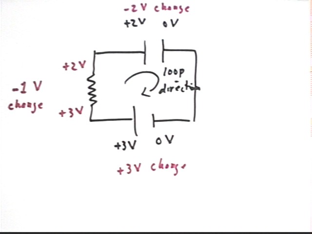
As indicated below we pick a direction around the loop formed by the circuit and determine potential differences in the direction of the loop. We can make the loop clockwise or counterclockwise; either way the change in voltage as we go completely around the loop must be zero, since no work is required to move from our original point to itself.
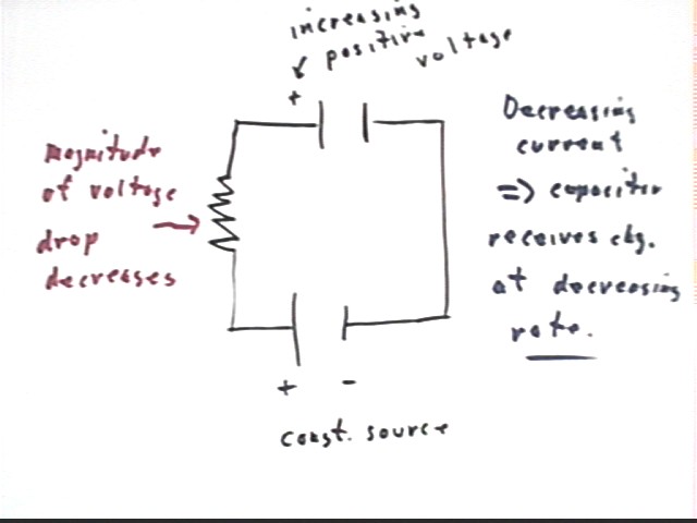
This shows us that if the potential difference across the source is positive then the potential difference across the charging capacitor is negative, and vice versa. The magnitude of the potential difference across the resistor is therefore the difference in the magnitudes of the voltages of the source and the capacitor. As a result the voltage across the resistor decreases as the charge on the capacitor increases.
The numerical example shown below indicates a +3 V change in potential across the source and a -2 V change across the capacitor as we move around the loop in the indicated direction. The net change around the circuit is zero, so the change across the resistor must be -1 V.
Does the voltage across the capacitor increase at a constant, an increasing or a decreasing rate?
Answer: As charge on the capacitor increases, the magnitude of the voltage drop across the resistor decreases. The current across the resistor therefore decreases.
Since it is the current which carries charge to one plate of the capacitor and away from the other, the decreasing current means that charge accumulates on the capactor at a decreasing rate.
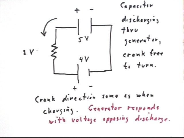
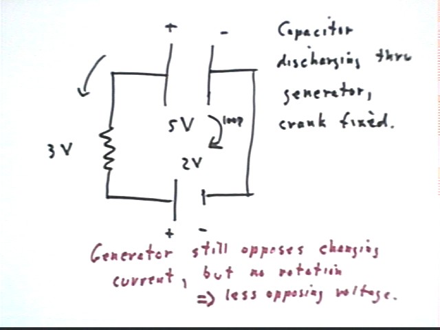
When the capacitor is allowed to discharge through the generator, with crank allowed to rotate freely in response to the resulting current, how does the behavior of the circuit differ from the behavior you observed when the crank was held stationary? Why do you think the comparison is as it is?
Answer: As you have observed the voltage across the capacitor decreases slowly when the generator is allowed to 'crank' freely--more slowly than if the handle of the generator is held stationary. The slow decrease becomes slower and slower as the voltage continues to decrease.
We also observe that the crank moves in the same direction as when the capacitor was being charged. When the crank moves in this direction the generator produces a voltage that tends to push charge toward the capacitor, at the same time the capacitor is pushing charge away. These opposite effects slow the net current flowing from the capacitor more than if the crank was held stationary.
It can seem somewhat ironic that the capacitor, in the process of discharging, should cause the generator to generate a voltage opposing it.
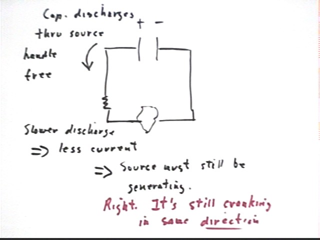
When the capacitor is allowed to discharge through the generator, with crank held still, does the current decrease at a constant, an increasing or a decreasing rate? Why do you think it behaves as it does?
Answer: As observed the current decreases at a decreasing rate.
Note that the generator doesn't actually have much resistance; rather, as we will see, the changing current changes the magnetic flux in the coil of the generator, resulting in a voltage that opposes the decrease in current.
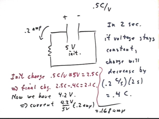
Suppose that the resistance R of the circuit remains constant. If the capacitor discharges through this circuit, then if the current is .2 amps when the voltage across the capacitor is 5 volts, what do you expect would be the current when the voltage across the capacitor is 2 volts?
Answer: A 5 V initial voltage will result in .5 C / V * 5 V = 2.5 C of charge on the capacitor.
A current of .2 amps means that charge is being carried from the capacitor at the rate of .2 Coulombs / second.
In 2 seconds the change capacitor will therefore lose .2 C / s * 2 s = .4 C of charge.
This results in a charge of 2.1 C. At .5 C / V this indicates a potential difference of 4.2 V.
The actual decrease in charge and voltage will be a bit less than this, because the decreasing charge and voltage will result in decreasing current. So our 4.2 V is only a good approximation, not an exact value.
This process can be continued. Since the voltage on the capacitor is now 4.2 V the rate of decrease will now be 4.2 V / (5 V) * .2 amp = .168 amp. Another 2-second time interval will therefore result in a decrease of about .336 Coulombs.
We can go on to calculate the new charge, and repeat the process.
If the capacitor holds .5 Coulombs of charge for every volt, and if the current is .2 amps at the instant the voltage across the capacitor is 5 volts, then what do you estimate is the charge on the capacitor 2 seconds later? Will your answer be an underestimate or an overestimate?
Answer: Do for next class.
If the capacitor holds .5 Coulombs of charge for every volt, and if the current is .2 amps at the instant the voltage across the capacitor is 5 volts, then how long do you think it will take the voltage of the capacitor to drop from 2.2 volts to 1.8 volts? Will your answer be an underestimate or an overestimate?
Answer: Do for next class.
If capacitance is .0100 Farad, meaning that the capacitor holds .0100 Coulombs of charge for every volt, and if the resistance in the circuit is 200 ohms, then how long do you estimate will it take the charge to fall from .0500 Coulombs to .0400 Coulombs?
Answer: Do for next class.
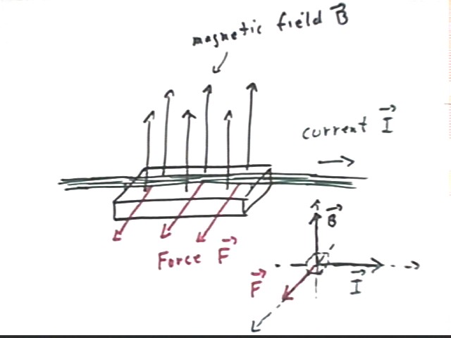
If current is flowing in the horizontal direction and the magnetic field is vertical and upward then what will be the direction of the force exerted by the magnetic field on the current?
Answer: We have observed that when current is run through a thin aluminum strip just above the center of a rectangular ceramic magnet the strip is deflected to the right or left.
Since the field of the magnet is at points very near the magnet directly away from its face, we see that the force exerted on the current appears to be perpendicular to the current.
Refined experiments confirm that this is the case. The precise direction (i.e., in this case right or left) is found by the right-hand rule (fingers in direction of current, palm facing so that when fingers are curled they curl toward the direction of the magnetic field; the thumb points in the direction of the force). For the field and current directions indicated below the force is as indicated, lying in the plane perpendicular to both current and field.
If current is flowing in the horizontal direction and the magnetic field is horizontal to the East then what will be the direction of the force exerted by the magnetic field on the current?
Answer: Do for next class.
If current was flowing in the upward vertical direction and the magnetic field was horizontal and to the North then what would be the direction of the force exerted by the magnetic field on the current?
Answer: Do for next class.
How much current did you run through the aluminum strip when you estimated the force, and how much force resulted?
Answer:
What was the length of the magnet?
Answer: Do for next class.
If force is F = I L B, where I is current, L the length of the current segment affected by the magnetic field and B the magnetic field, then what is the magnetic field of your magnet?