"
Physics II
Class Notes, 2/15/99
Video Clip #01
When we observe sound waves using the oscilloscope or
the simulation of standing waves in a string, the wave
patterns are typically much more irregular than a simple
sine wave.
- The apparent irregularity is mostly due to the presence of multiple
harmonics.
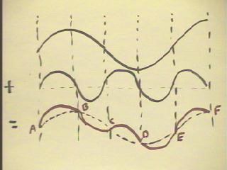
- As an example, the figure below shows a first harmonic of a string at
the top, a second harmonic (whose wavelength is half that of the first)
in the middle and the sum of the two harmonics at the
bottom.
- We see how the addition of these waveforms superimposes the
second harmonic on the first.
- At points A, B, C, D, E and F, the second harmonic has
displacement 0 from its equilibrium position and hence adds
nothing to the first, so that at these points the graph of
the sum coincides with a graph of the first
harmonic.
- Between A and B, the second harmonic is positive,
so the graph of the sum is higher than
that of the first harmonic; the same is true between C and D and between
E and F.
- Between B and C, the second harmonic is negative so
the graph of the sum is lower than that
of the first harmonic; the same is true between D and E.
- The pattern between A and E will be repeated again
and again.
Similar methods can be used to superimpose third, fourth and higher
harmonics on the first two.
The relative amplitudes of
the different harmonics yield different waveforms characteristic
of different voices and different instruments.
Video Clip #02
Video Clip #03
Video Clip #04
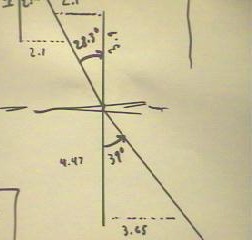
The rough outline in the figure below depicts a rectangular
tray full of a liquid consisting mostly of water.
- The line perpendicular to the side of the container is
called the normal line.
- The line at a 39 degree angle with the normal line depicts the path
of a light beam from a laser pointer as it passes through the
boundary of the container and enters the fluid.
- We see that the beam makes an angle of approximately 28.3 degrees with
the normal line after it has entered the fluid.
- The angles were obtained by measuring the indicated
distances on the figure (distances are in cm), then using simple
trigonometry to determine the angles.
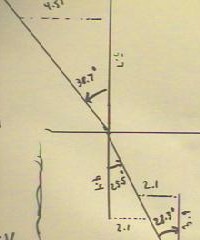
The angles with normal as determined by measurements
of sides of triangles were 25.5 degrees and 38.7
degrees.
- Ideally the 28.3 degree and 25.5 degree angles should
have been equal, as should the 39 degrees and 38.7
degrees.
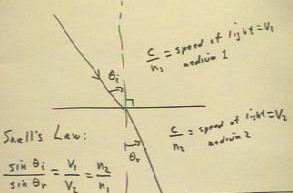
Snell's Law states that the sines of the incident
and refracted angles `thetaI and `thetaR should
be in the same ratio as the velocities of the light
beam in the two media.
- If the figure below depicts light moving from air into water,
then since light travels more slowly in water the angle
`thetaR should be less, as it is in the figure as sketched.
- The speed of light in a vacuum is generally denoted
c (and is equal to very nearly 3 * 10^8 m/s).
- The speed of light in any material will be less than c;
we generally denote the speed of light in a material as c / n, where n
is a number called the index of refraction of that material.
- The ratio of velocities is therefore inverse to the ratio
of indices of refraction.
Video Clip #05
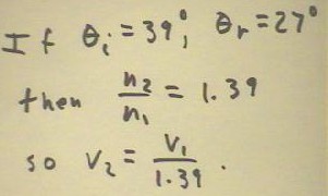
If we use `thetaI = 39 deg and `thetaR = 27 deg (averaging
the two supposedly equal values of `thetaR from the figure above), we obtain sin(`thetaI)
/ sin(`thetaR) = n2 / n1 = 1.39, implying that the velocity v1
in the water is 1 / 1.39 = .7 times (approx.) that in
the air.
- Accepted values of n for air and water are
approximately 1.0003 and 1.33, which would yield n2
/ n1 = 1.33.
- 1.39 is an acceptably close approximation of
the more accurate ratio 1.33.
Video Clip #06
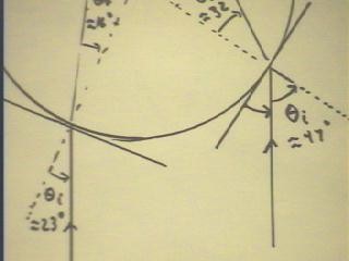
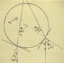
Observations of rays entering a circular
container full of water are depicted below.
- We see two rays entering the fluid from parallel directions,
one ray making an angle of 47 degrees in the other an angle of 23 degrees with the
respective normal lines.
- The normal lines will be lines tangent to the circle
and hence will be radial from the center of the circle.
- The angles of refraction are observed to be approximately 16 degrees
and 32 degrees.
- We see that the directions of the two refracted rays are
changed so that if they continue along the indicated
path, they will converge at a point.
The rays will not continue along the indicated path after
exiting the material; they will still come together, but
will not converge as quickly as would be indicated by the figure.
Video Clip #07
We consider what would happen if the rays were permitted to continue
indefinitely in the same material.
- In the figure below we show three
parallel rays, one of which is directed toward the center
of curvature (indicated by the * at the center) of the part of the circle shown.
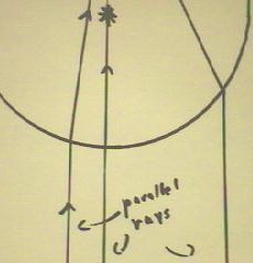
It can be shown from the geometry of the circle that all
parallel rays would meet near a single point,
called the focal point.
- Rays falling on the curved surface further from the central ray
will focus further from the focal point.
- Parallel rays falling within .1 * radius of the central ray will
focus very close to the focal point.
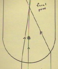
For a clear circular container full of water,
with the container surrounded by air, the focal point outside of
the container will lie very close to 1 radius
beyond the container.
- If the index of refraction of the liquid in the
container is n, then the focal point will lie at
distance r * (2 - n) / (2n - 2) on the other side of
the container.
- The position of the focal point can be observed
by moving a laser pointer back and forth in
front of the container, creating parallel beams, and finding the distance
at which a screen must be placed behind the container in order
to keep the transmitted 'dot' stationary.
Video Clip #07
"
