"
Physics II
Class Notes, 4/07/99
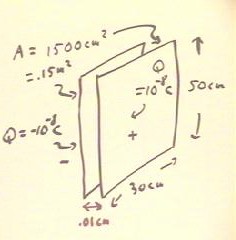
We analyze a capacitor consisting of two parallel plates, each 50 cm by 30 cm and
uniformly separated by .01 cm.
- We assume a charge of +- 10-8 C on the two plates.
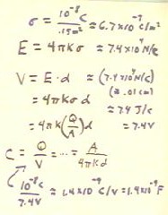
The charge density will tell us the electric field strength, which with the separation
of the plates will tell us the voltage between the plates, from which with the charge on
the plates we can determine the capacitance of the system.
- The charge density, 6.7 * 10-7 C / m2, is found in the first line
by dividing the charge of the plates by the area of the plates.
- In the second line we find the electric field to be 7.4 * 104 N / C.
- In the next three lines we determine the voltage, both symbolically and numerically.
- The 7.4 * 104 N / C electric field and the .01 cm distance gives us a 7.4 N m
/ C = 7.4 J / C = 7.4 V potential difference between the plates.
- The capacitance is found symbolically and numerically.
- Numerically, the 10-8 C charge corresponding to the 7.4 V potential
difference gives us a capacitance of 1.4 * 10-9 C / V = 1.4 * 10-9
F.
Video Clip #01
We can explain how a voltmeter measuring the voltage across a capacitor shows a voltage
which keeps increasing, but at a decreasing rate.
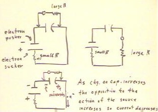
In the figure below we depict, on the left-hand side of the figure, a circuit
consisting of a capacitor in series with a voltage source. In parallel with the capacitor
we have a voltmeter, which consists of a coil in a magnetic field and a large
resistance.
- The negative terminal of the source repels, or 'pushes away' electrons while the
positive terminal 'pulls' electrons toward it. As a result, electrons will be pulled from
the positive plate of the capacitor and pushed to the negative plate.
- As this process continues the charges on the capacitor plates continue to build, but the
increasing voltage across the capacitor opposes the voltage of the source, tending to push
and pull electrons in the direction opposite to that of the source.
- This increasing voltage is read on the voltmeter.
- As a voltage read on the meter increases, the net voltage around the circuit decreases
and the current through the circuit therefore decreases.
- The current in the circuit tells us how fast charge is built on the capacitor.
- Thus as the voltage indicated on the meter increases, the voltage will increase at a
decreasing rate.
Video Clip #02
The figure at upper right in the figure above depicts a voltmeter connected in parallel
with a capacitor.
- In this case the large resistance of the voltmeter greatly reduces the current around
the circuit and therefore the rate at which the capacitor builds charge.
- The voltmeter will in this case have a larger current flowing when the charge across the
capacitor is small.
As the charge on the capacitor increases, the current through the voltmeter will
decrease and when the capacitor is fully charge the current through the voltmeter will be
zero.
It will take a long time to observe the decrease of current; since the current flow is
small the rate of transport of charge between capacitor plates will be small, so it will
take a long time for charge to build up.
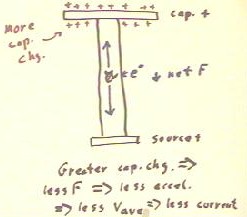
The figure below depicts an electron in a wire connecting a source and a capacitor. The
circuit is assumed to be complete.
- We assume that the charge in the capacitor fairly small, so that the voltage of the
capacitor is considerably less than that of the source.
- The electron is attracted to the positive terminal of the capacitor and to the positive
terminal of the source, but since the source voltage is higher than that of the capacitor
the net force on the electron is toward the source.
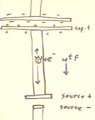
As charge builds on the capacitor, an electron in the wire will be more and more
strongly attracted to the capacitor and will therefore experience a smaller and smaller
net force toward the source.
- The result is that for greater capacitor charge the electrons in the wire drift more and
more slowly toward the source, and current in the circuit therefore decreases.
Video Clip #03
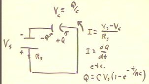
In a series circuit consisting of a source with a small resistance and a capacitor, the
voltage across the capacitor is related to the charge on the capacitor by VC =
Q / C.
- The current in the circuit is equal to the net voltage divided by the resistance of the
circuit.
- The net voltage is the difference between the source and the capacitor voltage, so the
current is (VS - VC) / R.
- The current is the rate at which charge moves through the circuit.
- Charge moves through the circuit by being pulled off of one capacitor plate and pushed
onto the other.
- As a result the current is the rate at which the charge on the capacitor changes.
- We state this rate relationship as I = dQ / dt.
- We therefore have dQ / dt = (VS - VC) / R = (VS - Q/C)
/ R, or
- dQ/dt = VS / R
- Q / (R C).
- The solution to this equation consists of the function Q(t) describing the charge of the
capacitor as a function of time. To obtain the solution we must use the techniques of
calculus.
- University physics students can verify that the solution to the equation is
- Q(t) = C VS -(
1 - e^(-t / (RC) ).
- This function describes an
exponential increase in charge, starting with Q = 0 at t = 0 and approaching a limit of C
VS as t gets large (i.e., after a long time has passed).
- A 'long time' for this circuit is
many times the time constant RC. At t = 10 RC, the charge on the capacitor will be
greater than 99.99% of the limiting value Q = C VS.
Video Clip #04
"
