"
Physics II
Class Notes, 4/09/99
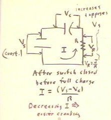
We observe that when we crank the generator at a constant speed through a series
circuit containing an initially uncharged capacitor and a small resistance (perhaps just
the internal resistance of the generator), cranking gets easier and easier.
We explain this as follows:
- The increasing charge on the capacitor increases the voltage across the capacitor.
- The voltage across the capacitor opposes the voltage of the source and therefore the
current in the circuit decreases.
- Less current flowing through the resistor dissipates less power.
- Cranking at a constant rate, less power implies less force and therefore easier
cranking.
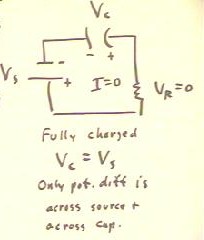
If we have a fully charged capacitor, then the voltage VC across the
capacitor is equal and opposite to the voltage VS across the source and the
voltage VR across the resistor zero.
- There will therefore be no current flow in the situation.
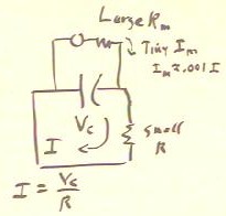
If we discharge a capacitor through a relatively small resistance, such as the
resistance of the generator, we can measure the voltage across the capacitor with a
voltmeter.
- We connect the voltmeter in parallel across the capacitor so that its large resistance
will not interfere with the flow of current.
- In this configuration its large resistance will prevent the flow of a significant amount
of current through the meter.
- The tiny current that remains will deflect a coil of the meter to give us our voltage
reading.
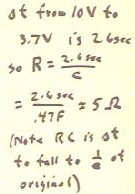
For a .47 Farad capacitor we observe that the voltage falls from 10 volts to 3.7 volts
in 2.6 seconds. We use this observation to estimate the resistance through which the
capacitor is discharging.
- The capacitor falls to 1 / e = .37 of its original value, so its time constant RC is the
corresponding 2.6 seconds.
- It follows that the resistance is approximately five Ohms.
Video File #01
We note that if we allow the capacitor to discharge through the generator, it
discharges much more quickly if we do not allow the crank of the generator to turn.
- This is because when the crank turns the coil in the generator it produces a voltage
opposing the tendency of the capacitor voltage to decrease.
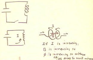
- A similar situation would occur if we had a source connected in series with a coil, or
an inductor, as indicated below.
- When the switch is closed and current begins to flow, the current in the coil tends to
increase.
- Since the current in the coil produces a magnetic field, the increasing current produces
an increasing magnetic flux in the coil.
- The increasing magnetic flux causes a voltage d`phi / dt.
- This induced voltage opposes the change in current, thereby slowing the change.
Video File #02
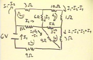
The circuit below consists of a 6 V source in a multiply branching circuit
including resistances of 9 Ohms, 8 Ohms, 3 Ohms, 10 Ohms, 1 Ohm, 6 Ohms, 5 Ohms, 3 Ohms
and 4 Ohms.
- We wish to determine the current through each resistor.
- We will make use of Kirchoff's Laws, which state that
- The algebraic sum of the currents into any branch point is zero.
- This is common sense, because electrical charges cannot accumulate at a branch
point--their mutual electrostatic repulsion prevents accumulation.
- The sum of the voltage drops around any closed loop is zero.
- This condition expresses energy conservation--a charge taken around the loop ends
up at its starting point, at the same potential it started with, so there is no change in
its potential.
- We first assume a current through each resistor. We choose an arbitrary
direction for each current; if we choose the 'wrong' direction our solution will indicate
a negative current.
- We write the currents in terms of as few unknowns as possible.
- We start with current I1 through the 9 Ohm resistor and the source.
- This current branches into I2, through the 8 Ohm resistor, and another current
through the 3 Ohm resistor.
- We use I2 for the current through the 8 Ohm resistor; the remainder of the I1
coming into the branch point is I1 - I2, and goes through the 3 Ohm resistor.
- At the next branching point, I1 - I2 splits into I3 and I1 - I2 - I3.
- I3 joins with I2, and splits into currents I4 and I2 + I3 - I4.
- I4 joins with I1 - I2 - I3, with I1 - I2 - I3 + I4 leaving the branch point.
- We have four unknowns, I1, I2, I3 and I4.
- We will need four equations to solve for these unknowns.
- We choose four independent loops L1, L2, L3 and L4 as shown, and we indicate a
direction around each loop.
Video File #03
Next we write the equations for the voltage drops around each loop.
- Around the first loop we have a 6 Volt drop through the source (the direction of
the loop is from the positive to negative terminal of the source); the current I1 through
the 9 Ohm resistor results in a drop of 9 Ohms * I1; I2 through the 8 Ohm resistor results
in a drop of I2 * 8 Ohms; and the current I2 + I3 - I4 through the 4 Ohm resistor results
in a drop of (I2 + I3 - I4) * 4 Ohms.
- The total of these drops is zero, giving us the first equation.
- The remaining three equations express the voltage drops (always zero) around the
remaining three loops.

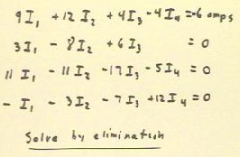
We simplify the equations by collecting terms and dividing through by the unit
Ohms. We arrange the equations so that the four unknowns are lined up in columns,
and we move the 6 amps (6 Volts / Ohm) on the right-hand side.
These equations can be solved by elimination or by some other method to obtain
the currents I1, I2, I3 and I4.
- The solutions, rounded to 2 significant figures, are I1 = -.40 amps, I2 = -.21
amps, I3 = -.08 amps, I4 = - .14 amps.
- I1 - I2 is therefore -.19 amps; this is the current through the 3 Ohm resistor.
- I1 - I2 - I3, through the 10 Ohm and 1 Ohm resistors, is -.11 amps.
- I2 + I3 - I4, through the 4 ohm resistor, is -.15 amps.
- I1 - I2 - I3 + I4 is -.25 amps.
- All these currents are negative, so the directions chosen for the currents are
all wrong. The currents actually flow in the opposite direction in each case.
Video File #04
"
