"
Physics II
Class Notes, 4/14/99
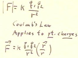
Coulomb's Law applies only to point charges.
- This law applies approximately when the charges are approximately point charges (i.e.,
when the charges are distributed over a region which is small compared to their
separation).
- This law does not, for example, apply to the charges on capacitor plates, which are
distributed over a region which is large compared to the separation of the charges.
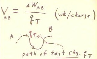
The potential difference between two points A and B is the work per charge required to
move a charge of from A to B.
- It is shown using multivariate calculus that this work is independent of the path from A
to B.
- The electric field is therefore said to be 'conservative'.
Video File #01
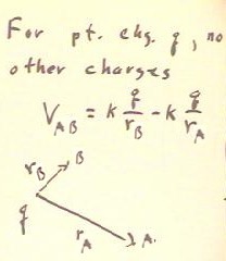
For a point charge q, the potential difference between points A and B depends only on
the distances of points A and B from q.
- If rA and rB are the respective distances then it turns out that the potential
difference is the difference between the quantities k q / rA and k q / rB, as indicated
below.
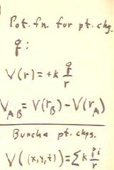
- This motivates the definition of electrostatic potential as V(r) = k q / r.
- We could write VAB = V(rB) - V(rA).
For a large number of point charges qi the potential at the point (x,y,z) is the sum of
the potential differences k qi / ri, where ri is the distance of qi from (x,y,z).
Video File #02
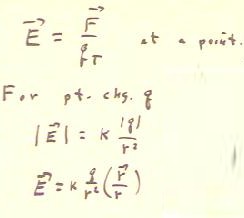
The electric field a point is defined as the force per unit charge experience by a test
charge at the point.
- For a point charge the magnitude of the electric field at a point P lying at distance r
is k | q | / r^2 and the direction is that of the vector r / r or of its opposite,
where r is a vector from the position of q to the point P.
- When k q / r^2, whose magnitude is that of the field but which is negative or positive
as q is negative or positive, is multiplied by this vector we get the electric field
vector.
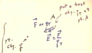
If a test charge qTest experiences a force F at a point A, then the electric
field at that point is E = F / qTest.
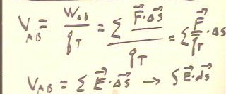
As seen before the potential difference between two points A and B is obtained by
adding up the work contributions Fperpendicular `ds for some path between A and B.
- This is the same a setting up all the Fperpendicular / qTest `ds contributions.
- Since Fperpendicular / qTest = Eperpendicular, we see that this is the same a setting up
all the Eperpendicular `ds contributions.
- In the limit this process gives us the integral of Eperpendicular `ds over some path
between A and B.
Video File #03
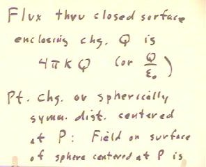
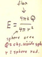
The electrostatic flux through close surface enclosing a charge Q is 4 `pi k Q.
- For a point charge or spherically symmetric distribution centered at some point P, then
electric field centered on a surface of a sphere whose center is at P is both uniform and
perpendicular to the surface.
- It follows that the electrostatic field at every point of the sphere is perpendicular to
the surface and equal to the flux through the surface divided by the area of the surface.
- The resulting expression for E is E = k Q / r^2.
- Thus we see that when a charge is spherically symmetric about a point P, then for any
other point A the electric field can be calculated by using Coulomb's Law on the amount of
charge enclosed by a sphere through point A and centered at P.
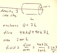
If a uniform line charge density `lambda is distributed in a long straight line, then a
cylinder of radius r whose axis is along the line and not near either end of the line
distribution will experience flux of through only the curved side of the cylinder.
- Since the cylinder in closes charge Q = `lambda L, the total flux is 4 `pi k `lambda L.
- When this flux is divided by the area of the curved side, we find the field is 2 k
`lambda / r.
- Note that where for a spherically symmetric distribution the field was proportional to
the inverse square of the distance, for the line distribution the field is inversely
proportional to the first power of the distribution.
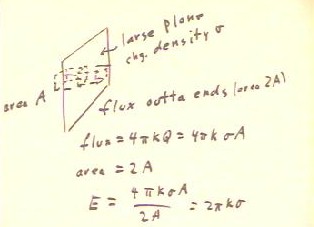
For a large plane region where charge density is `sigma, a rectangular box with
cross-sectional area A will enclose charge `sigma A and thus experience flux 4 `pi k
`sigma A.
- By the symmetry the situation the field in any region which is much further from the
edges of the distribution than from the plane is everywhere perpendicular to the plane.
- It follows that the flux passes through area 2 A and the electric field is therefore 2
`pi k `sigma.
- Note that this field does not depend on distance from the distribution.
Video File #04
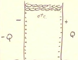
For two plates with area A, with charge Q uniformly distributed over one and -Q over
the other, we have charge densities `sigma = +- Q / A.
- This results in electric field of magnitude 2 `pi k Q / A directed away from the
positively charged plate, and another of equal magnitude toward the negatively charged
plate.
- The result is an electric field E = 4 `pi k Q / A between the plates, directed for the
positive to the negative plate, and no field outside the plates.
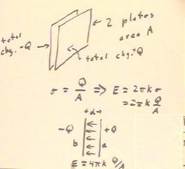
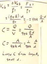
The voltage between the capacitor plates is easily found to be 4 `pi k Q/A * d.
- The capacitance, being the ratio of charge to voltage, is therefore (1 / ( 4 `pi k ) ) *
A / d.
Video File #05
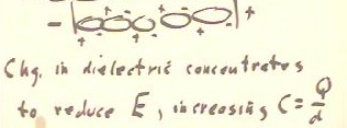
If space between the plates of a
capacitor is filled with a material whose molecules tend to align with electric field (a
dielectric material), the result can be a reduction in the electric field between the
plates for a given charge Q on the plates.
- This effect occurs when the charge
in the dielectric concentrates a net negative charge at the positive plate adding that
positive charge the negative plate.
- The decrease in electric field
decreases the voltage V for given charge Q and hence increases the capacitance C.
Video File #06
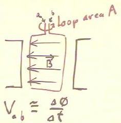
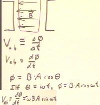
The figure below depicts a loop of area A rotating in a magnetic field B directed
perpendicular to the axis of the loop.
- The changing magnetic flux results in a potential difference between the points a and b.
- Over short time interval `dt, the average potential difference will be the average rate
which the magnetic flux through the loop changes.
- At any instant the potential difference will be the derivative of the flux with respect
to time.
- If the angle `theta which describes the angular position of the rotating loop is
changing at constant rate `omega (i.e., if the angular velocity of the loop is `omega),
then the flux at clock time t is B * A * cos(`omega t).
- Calculus-literate students will verify that the resulting derivative is -`omega B A
sin(`omega t).
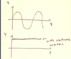
The hand-held generator used for the experiments works by rapidly rotating a loop of
wire between the poles of two magnets.
- This should give rise to an alternating voltage, such as that shown in the top the graph
below.
- Electronic devices within the generator invert this alternating voltage into an
approximately constant voltage.
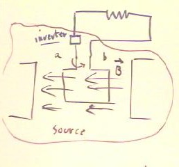
The generator can be represented by the 'source' region enclosed in within the red
curve of the figure below.
- This figure depicts the source connected in series with a resistance.
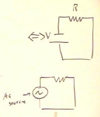
This picture is represented as a voltage source in series with the resistance, as in
the figure below.
- Had the voltage of the source not been inverted, we would have had a source of
alternating current, often symbolized as at the bottom of the figure below.
Video File #07
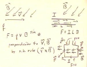
A charge q moving at velocity v
in the presence of the magnetic field B will experience a force q v B sin(`theta),
where `theta is the angle between the velocity of the charge and the magnetic field.
- The direction of the force will be perpendicular to both v and B, with its
direction determine by the right-hand rule.
- The vector form of this relationship is in terms of the cross product v X B: F =
q * v X B
For a current in a wire, the total of all the q * v contributions from the drifting
charges is equal to the product I * L of the current in the length of the wire, so when
the magnetic field and the wire are perpendicular the force is F = I L B, with the
direction of the force determine by the right-hand rule.
- If the field and the wire are are not perpendicular then F = I L B sin(`theta), where
`theta is the angle between the field and the wire.
The net forces on a current loop, when the loop is oriented so that the magnetic field
direction is in the plane of the loop as indicated below, give rise to a torque about the
axis of the loop.
- Had the loop been or oriented perpendicular to the magnetic field the torque would have
been 0.
Video File #08
"
